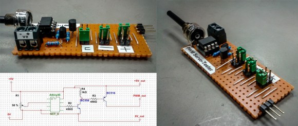
Having the right tool for the job makes all the difference, especially for the types of projects we feature here at Hackaday. [Jana Marie] must agree with this sentiment, one of her latest projects involves building a tool to generate a PWM signal and test servos using an Attiny25/45/85.
Tools come in all kinds of different shapes and sizes. Even if it might not be as widely used as [Jana’s] earlier work that combines an oscilloscope and signal generator, having a tool that you can rely upon to test servos and generate a PWM can be very useful. This well written Instructable provides all the details you need to build your own, including the schematic and the necessary code (available on GitHub). The final PWM generator looks great. For simple projects, sometimes a protoboard is all you need. It would be very cool to see a custom PCB made for this project in the future.
What tools have you build recently? Indeed, there is a tool for every problem. Think outside the (tool) box and let us know what you have made!


Speed reading tool?
Only tools think that works,
That really depends on what you mean by it. You can probably learn to read the words at a very high rate but most people wouldn’t be able to comprehend the data at that rate.
Good for finding the information you need faster. Or reading nonsense text such as economic science literature and only remembering the actual facts.
I can skim at a bajillion words per minute, I’ve no idea what any of them were. Doesn’t matter, as it turns out.
I’m glad to offer HaD readers a huge .99% discount off my speed reading course.
“Why comprehend? That just slows you down on the way to the reply box.”
http://imgur.com/a/UlZ6W
Retention however, I have no idea about, but you can easily do 250WPM this way.
These aren’t that impressive. 250 wpm is pretty slow. Try one of the ‘normal’ speedreading tests online. 500+ should be easily achievable, and about 800 only takes a little practice
This could be done with a 555 time
i thought the same, using an mcu is overkill in my book.
Why is it every time someone builds something there is always someone who has to post that it could have been done a different way? Who cares? If you want to use 555 timers in your project then feel free. If he is more comfortable using attiny’s then let him. Maybe he just happened to have an extra attiny. Maybe he didnt have the right passives to make the 555 work. Maybe he just wanted to expand his horizons. Its the most childish viewpoint to think everyone has to do it the same way or that your way is always the right way. Oh and dont bring up price. Ive bought attiny85’s for less than 555’s.
I actually did build a couple of these using 555s. I agree, it’s probably not cheaper, especially when you consider all the passive parts. However, it is the right way to do it (from my point of view) because it makes the design as simple as possible.
I’d have to disagree with you there, the timing is pretty critical and getting an asymmetrical PWM wave form adjustable and stable isn’t the easiest on a 555 while it is literally child’s play on a micro. You could even throw in some averaging to filter out noise on the analog input. If you used a crystal you would have stability down in the ppm region.
It’s actually not difficult, you use a 556 or two 555s. One in monostable and one in astable, as the trigger for the other. You just use a pot to adjust the RC constant on the monostable vibrator and thus pulse width. I know it’s not a popular opinion but I will always prefer a simple analog solution to one that involves microcontrollers and programming, even though (perhaps because?) I’m a programmer by occupation. I have a deep hatred of adding more complexity than is needed to anything.
@novak
So let me get this straight, you’re saying using more components (especially two 555s) is somehow simpler than a uC and a tiny bit of software? I know it may seem like a “waste” considering just how powerful these little uCs are, but not only do they simplify the circuit, it ends up being cheaper overall too. I came to this realization when I was designing my own servo controller. Granted, mine has a bit more functionality which was necessary for the project, and I did feel a bit guilty initially about using a uC, but elegance is in overall simplicity which is what a uC provides. Lastly, silicon is silicon, so what makes a 555/6 more appropriate?
I’m not trying to start a holy war, I did say it was my opinion. But yes, that is much simpler. A 555 is several orders of magnitude simpler than even a simple micro controller, with probably a couple dozen transistors vs 10s or 100s of thousands (potentially millions?), not sure exactly where an ATtiny falls.
Novak, I’d have to disagree with you too. I have built one using only an Attiny13, no passives with a sweeping feature that spins a servo through its range and then change it to move to each end limit and then back to center. That takes less lines of code than it takes in parts via analog. 555 is in no way simpler, unless analog is all you know.
I guess the distinction I’m trying to make is between “simple” and “easy.” But either way obviously works.
I would have agreed it was overkill, but for a smaller footprint (dip8) you can have a tiny13 do 2 channels and have completely proper timing, with no fuffing around trying to find a capacitor thats 3% over tollerance to get the timing right when the chip is 26degrees C. Yes, microcontrollers are nice.
Oh the religious wars, just not enough of them in this world.
I would be using a Z80 CPU with and the control pins tied to their inactive state and the data bus pins pulled low to force the CPU into NOP cycles. Then have a high address pin connected through a capacitor to some diodes that then feed into the data bus to force a Jump instruction(&hC2 from memory). As the following two reads will be ’00’ then it will force a Jump to ‘0000’ like reset.
Of course this will produce a fixed frequency output on the output address pin so I would drive the clock signal with a 555 that is adjustable in frequency. Then there is the other half of the signal needed so I would just have a second CPU setup the same way.
This is by far the simplest way as no coding is required LOL!
But seriously lol, I love to see people doing things ‘differently’. How boring would this site be if we all ‘religiously’ did things the same way!
You can get servo testers for a couple of dollars off eBay.
No coding, no soldering, no wondering what chip to use…
If I read his schematics and code correctly, he is sending a 500 Hz PWM signal of between 0% to 100% duty cycle through a transistor. That’s useful to drive a lot of different things, but not servos.
The common servo takes a 1ms to 2ms pulse every 20 ms, and the length of the pulse decides the position. The signal doesn’t need a transistor, as it is only a signal and the power is drawn from the power and ground lines.
Most servos actually accept between 500 and 2500 µs, this is because 1-2ms is the definition for a 90 degree movement and most servos go closer to 180 degrees. Still that means this contraption would only make use of 10% of the potentiometer. Maybe if there was a switch to select servo or regular PWM?
source with makefile, tiny13; 2 analog channels in, 2 hobby servo pwm channels out. (.9ms to 2.5ms)
http://ruemohr.org/~ircjunk/tutorials/prog/servoControl2/
Pretty sure I submitted this and never heard anything.