Diode matrices were one of the first methods of implementing some sort of read only memory for the very first electronic computers, and even today they can be found buried deep in the IPs of ASICs and other devices that need some form of write-once memory. For the longest time, [Rick] has wanted to build a ROM out of a few hundred diodes, and he’s finally accomplished his goal. Even better, his diode matrix circuit is actually functional: it’s a 64-byte ROM for an Atari 2600 containing an extremely simple demo program.
[Rick] connected a ton of 1N60 diodes along a grid, corresponding to the data and address lines to the 2600’s CPU. At each intersection, the data lines were either unconnected, or tied together with a diode. Pulling an address line high or low ([Rick] hasn’t posted a schematic) pulls the data line to the same voltage if a diode is connected. Repeat this eight times for each byte, and you have possibly the most primitive form of read only memory.
As for the demo [Rick] coded up with diodes? It displays a rainbow of colors with a black rectangle that can be moved across the screen with the joystick. Video below.


I wonder what kind of power consumption and propagation time we’re talking about here?
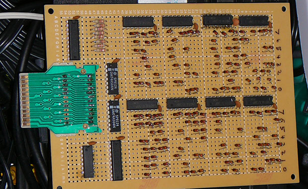
The back looks like a mess, though. Since the diode array has a very regular structure, it should be possible to do a much nicer job.
Frankly it looks like he has done a pretty good job, please elaborate on your improved scheme–he has the vertical crossbars done with busses, and only the horisontal done with pretty short wires; I doubt that he could get a tighter density even with a dual layer PCB
For starters, I would have used stripboard http://en.wikipedia.org/wiki/Stripboard#mediaviewer/File:Stripboard.jpg so you can make the rows without wires. Only solder in one side of the diode, and then use a bare piece of wire to solder the colums on the component side.
Alternatively, mount the diodes vertically, and put another piece of stripboard across, sandwiching the diodes between the two pieces of stripboard. This will be very dense (100 bits per square inch), but obviously not suitable for modification afterwards.
Like this, for instance: http://geodesicsphere.blogspot.nl/2013/10/visualizing-roms-1-diode-matrix-rom.html
Rows on the bottom, columns on top. No messy wires.
You think than bad I am a radar tech form the 1980, it looks like some diode matrix we used in the radar system, that was originally designed in the 1960’s
Nice work! Pretty inspiring stuff, really.
Agreed! It’s always great to see this kind of thing. :D
Very very nice! this made me drool!
Why 1N60 Schottsky diodes? Would any diode, like the 1N4001 do the trick? What I mean is, why did you choose 1N60’s?
Why not use SMT circuit/board? IIRC there’s a few protoype SMT boards available out there. Pack more into the same space. A quick Google shows a couple of white sheets for 1N60’s in a SMD package so I guess they’re available somewhere.
Have you seen the backside? SMD makes wirewrapping…slightly harder.
Perhaps the voltage drop of regular diodes was too much?
If the diodes are used to program the zeroes (which makes sense with most decoder chips), a standard diode will have a bit too much voltage drop to meet the spec for a TTL low level.
In spite of that, I got away with it when I made a similar circuit in the late ’70s.
Mine was a three byte ROM, to insert a JMP instruction on the bus of an 8080 computer at startup, so the EPROM could be at a higher address than the reset vector.
1N60 is not a Shottky diode, just a germanium point-contact diode.
1N4001 may be too slow for this job – because of PN junction capacity and recover time.
IN4001 is a rectifier diode. It has huge capacitance because it is for higher current (1A) and for rectifying *slow* AC like 60Hz. You wouldn’t even want that for a switch mode power supply at hundreds of kHz let alone digital stuff at MHz.
You might want to use small signal *switching diodes* like those 1N914/1N4148 or schottky diode for applications like this.
This refresh my mind with my first logic project (based on DTL chips) : a 1024 bits ROM build with diodes and containing a morse message for an Ham beacon. 45 years ago…
+1 for homebrew ham equipment. :)
I experimented with Diode ROMs last year; http://geodesicsphere.blogspot.com/2013/10/visualizing-roms-1-diode-matrix-rom.html It was pretty darn fun, and it’s neat to SEE the data sitting there. It’s not something you can usually see. (I only did 4 bytes, and I wasn’t concerned about conserving space.)
Random thought of the day: I remember reading something about traffic light controllers using a diode card for the conflict monitor. If two perpendicular streets both show a green light due to a failure on the controller, the conflict monitor uses diodes to detect this, cuts out the normal controller and goes to a flasher circuit that shows flashing red on one side and yellow on the other.
If somebody can make sense of this, congratulations:
http://www.oregon.gov/ODOT/HWY/SIGNALS/docs/diodecardnew.doc
actual card:
https://connect.ncdot.gov/resources/safety/IT%20and%20Signals/Section%2007%20Conflict%20Monitor%20Programming%20rev.%202_12.pdf
enjoy,
http://arduinoenigma.blogspot.com