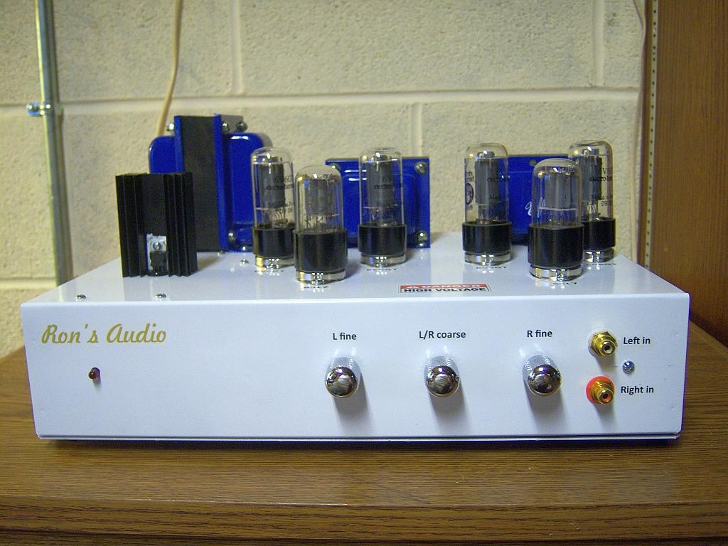
Most of the work that [Ron] has done in the past with vacuum tubes and solid state electronics has been repair. At 59 years old, he finally put together his own stereo tube amplifier and we have to admit it definitely has an awesome look.
The platform is built around the well-known 6V6 beam-power tetrodes which are mostly used by major audio brands for their guitar amplifiers nowadays. The Dynaco 6V6 circuit based PCB was bought from China and minor changes were made to it. The amplifier uses one transformer to convert the US 120VAC into 240VAC and 9VAC, the first being rectified by a glassware PS-14 power supply while the later is converted regulated at 6.3V for the tube heaters. The output stage consists of two Edcor audio transformers (one for each channel) that converts the high voltage for its 8 ohms speakers. The home-made chassis provides proper grounding and as a result you can’t hear any background noise.
We are very curious to know if some our readers have been experimenting with glass tubes for audio applications. Please let us know your experience in the comments section below.


I was always under the impression that the reason to use tubes in audio is for their “musical” distortion and that using feedback largely cancels that out and therefore largely defeats the point.
Tubes are still one of the most linear forms of voltage gain. Distortion is also even order giving it a slightly different sound. Feedback does not change that, and there are very few amplifiers on the market which don’t use feedback, and those that don’t typically sound like garbage regardless if they are tubes or SS.
Even-order harmonics are cancelled out in push–pull amplifiers.
And the VT vs SS debate rages on….
From his page “My advice to anyone thinking of doing so is first disregard 75% of what you read in the audio forums”
Without starting a VT Watts vs SS Watts argument, if playing outside and I have to crank my Selmer to the max the distortion is very desirable, if I crank a SS amp too far I will make people very sad
One approach nowadays is to use a 12AX7 or similar as a preamp, then send that through a modern “hybrid digital” amp like the TAS5630B. It gives the “tube sound” effect at a much lower cost and very high efficiency.
Also, for high power outdoor applications, it’s pretty easy to find MOSFETs (or IGBTs for subwoofer applications) that will do a few kW with only a little heatsinking.
I went one step further and removed the pre-amp. Driving my amp directly with a line level source made a huge improvement in the audio quality. Not subtle, but shockingly obviously.
In my case it was a Squeezebox 3 directly into a DNA125. The preamp was a Linn LK1. The DNA125 has a very high input impedance – 10K ohms, as I recall.
Apparently what I did is a popular thing and there are plenty of forum posts about different approaches. Strategies for impedance matching, and different methods of volume attenuation, are common topics. With a turntable as the source things are a bit more complicated.
Less is more.
Selmer, you play clarinet? Either way it was made in Elkhart Indiana. I have a bunch of old Conn tube amps.
Looks great Ron, nice job.
http://www.beavisaudio.com/projects/ValveCaster/
Not Hifi but a guitar amp with…. 0.25W output, Tube reverb and Tube vibrato… all built with pencil tubes. Check this out: http://www.verelec.nl/?page_id=29
I recently finished putting together a single ended valve amp based off the Tublelab design. It uses old Russian 6550s which reportedly have more bass than other tubes. I can honestly say it sounds wonderful- A highly recommended project for anyone who appreciates good sound quality. Pictures at the bottom of this page: http://oldschool.co.nz/2011/forum/index.php?/topic/30483-hipster-hi-fi-thread/page-24
This site requires a log-in.
Oops your right, sorry about that!
He did not design his own stereo amp, he stuffed two tube amp boards from a Chinese board shop. then included a pre-manufacturesd power supply.
Not as much of a big deal as his using angelfire as a page host.
http://www.frontiernet.net/~jff/SonOfSVPCL/DIYSVTBassPreamplifier.html
I’ve been scratch building tube guitar amps suchlike for 10 years. I just completed this ampeg svt-like preamp in a 1 U chassis. It has a real hack, too: I reverse engineered the custom multitapped toroidal inductor that gives the midrange tone control its special character. I published all my design and build documentation, so it’s ready for others to build.
I’m not a follower of the tube cult personally. I do not think tubes make any better amplifiers than they make computers. It is 2014 so move the fuck on already.
just recently built a headphone amp using a 5751 12ax7. found the tube burried in a barn and all the other parts i got for free except the 2 watt resistor. I have to say the sound is WONDERFUL. it does pic up any sound from the powersupply so using a battery sounds the best.
Today i just scored a couple thousand tubes from someone who just wanted to get rid of them! saw this and am excited cause i have alot of 6v6 tubes!
https://www.facebook.com/CRACKED1CE/posts/687766681302321
That actually looks pretty cool. Some serious potential there for a really, really cool enclosure. Consider putting that up on hackaday.io?
yeah. i love working with wood, just need to paint it. ill probably put it up when i get some time. lots of projects going on lately
Socket flanges topside soldered through PCB’s bottomside – and heaven help you if you ever want to access the backs of the PCB for service or mods. With bottomside socket flanges the boards can easily be demounted whole and can still be operated while loose.
There are good reasons why this form of phase inverter isn’t popular and was mostly found in “economical” radiograms and the like, but then you don’t get a lot of choice using a bought PCB rather than doing point-to-point wiring which is easy to change (to say a Long Tailed Pair, and no DC through the OPT secondary).
The 1500pF in the NFB seems about ten times too high. The right value depends on the OP transformer used and should be tweeked for best squarewave output into a resistive load.
The war is over, vacuume or solid state, components are just components (or are we going to start bagging Dekatron and Nixie clocks cos they aren’t LED’s or seven segment?).
About tubes or transistor. There is not much to say. You listen to the amp and if you like what you hear it’s a good amp FOR YOU. And about this being 2014. The discussion about this started in the 70/80th last century and therefore is old. You say old is bad, so – by your standards – you shouldn’t talk about it.
Your logic is a bit too simplistic. But thanks for playing!