[Craig] recently built himself a version of the “hassler” circuit as a sort of homage to Bob Widlar. If you haven’t heard of Bob Widlar, he was a key person involved in making analog IC’s a reality. We’ve actually covered the topic in-depth in the past. The hassler circuit is a simple but ingenious office prank. The idea is that the circuit emits a very high frequency tone, but only when the noise level in the room reaches a certain threshold. If your coworkers become too noisy, they will suddenly notice a ringing in their ears. When they stop talking to identify the source, the noise goes away. The desired result is to get your coworkers to shut the hell up.
[Craig] couldn’t find any published schematics for the original circuit, but he managed to build his own version with discrete components and IC’s. Sound first enters the circuit via a small electret microphone. The signal is then amplified, half-wave rectified, and run through a low pass filter. The gain from the microphone is configurable via a trim pot. A capacitor converts the output into a flat DC voltage.
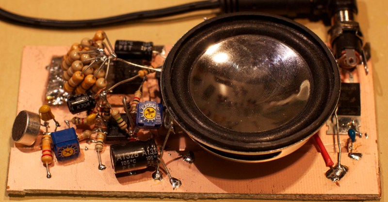
The signal then gets passed to a relaxation oscillator circuit. This circuit creates a signal whose output duty cycle is dependent on the input voltage. The higher the input voltage, the longer the duty cycle, and the lower the frequency. The resulting signal is sent to a small speaker for output. The speaker is also controlled by a Schmitt trigger. This prevents the speaker from being powered until the voltage reaches a certain threshold, thus saving energy. The whole circuit is soldered together dead bug style and mounted to a copper clad board.
When the room is quiet, the input voltage is low. The output frequency is high enough that it is out of the range of human hearing. As the room slowly gets louder, the voltage increases and the output frequency lowers. Eventually it reaches the outer limits of human hearing and people in the room take notice. The video below walks step by step through the circuit.


The Annoyatron 3.0!
Nicely done. I’m a fan of dead-bug and Manhattan circuits
http://clifford.soup.io/post/419436041/digital-every-idiot-can-count-to-one
more than the sound, the annoying thing to me is the way everything was put together and the way it was soldered…. my 7 year old daughter could of made it more tidy than that…..
You should make a hackaday.io profile for your daughter and show the world her elite skills.
I sure that we all could of.
Nobody is perfect. :)
I’m sure you could “of”, but could you *have* used proper English in your post? Apparently not…
annoying …
“Nobody is perfect. :)”
I think you mean “Nobody, is perfect!”
I am sure you meant “Nobody, is perfect!”
I’m sure nobody cares.
AFAIR was this kind of soldering style used for high frequency stuff in the old days
And in the new days, too.
how annoying does it have to be to make you go away?
Op amps don’t like driving capacitive loads.
With the gain being so high and the output being rectified the chance of oscillation from overshoot looks pretty slim.
This story reminds me of the TV Hassler a friend of mine made some years ago.
His trash upstairs neighbours kept their TV volume at deafening level 18 hours a day.
He put together a version of the Hassler that generated noise in the TV bands, triggered by the audio.
He mounted it on his ceiling and only switched it on when he was home.
The trash upstairs had the repair man along 3 fruitless times to fix their TV before they found that if they kept the volume down, they didn’t get picture interference.
Win. Wish I had thought of that for my last batch of neighbors.
The only annoying sound from my neighbour is when he is peeing in the middle of the night. I guess I can’t make him control his flow…
Brilliant.
Fun project. I’d use a piezo tweeter though, it’s louder, easier, more efficient. And in particular makes power resistors, homemade or otherwise, unnecessary.
Is that what that big wad of resistors is?
I thought it was a resistor tumour! Hope it’s benign.
I need it… for reasons… :D
Wow, such a cool little project and a FANTASTIC design review! Well done mate!
Seconded- design review was practical, straightforward and made me feel smarter than I am. Bravo!
How come this could not be based on a PC soundcard and a program? Like using HTML and the tag. The only thing to notice that most adult humans can not hear above 19 Khz. The most annoying would be around 400 Hz but would be easy for people to locate it by head tracking. Small children can hear upwards of 25 Khz (mosquito sounds). You could use looped WAV files that are in specific steps (no smooth transitions – only stepped). The microphone level would be tracked and sets the wav file to be played and it’s volume level.
This build is much simpler, and cost effective. A processor loaded with firmware is not always the best solution.
Oh, I do wonder how Bill’s response to this question would have gone…
It could be, but this approach is not. I don’t know if your question really demands any further explanation. Have fun building your app!
I have tried this. Soundcards typically run at 44.1Khz, allowing reproduction of frequencies up to 22.05Khz. Let’s say you want to target a 25 year old male, 16Khz is a good starting point for that. You get only 2.75 samples per cycle, and with so few samples/cycle, it tends to produce some lower frequency artifacts that become audible when played at the high volume required. These are more easily heard and located by the ear, often leading to the target rapidly discovering the source of the sound. I suppose you could add a high-pass filter, or use a better soundcard, but doing it in the manner presented avoids such issues from the start.
If your sound card produces low frequency artefacts on a 16 kHz tone, it’s broken.
Here’s a 16Khz sinewave, at 44.1Khz, normalized to 90% volume:
https://imagizer.imageshack.us/v2/788x440q90/661/XzmBGZ.png
The sinewave is superimposed, the square pips are the actual samples. Notice that’s there’s only a few of them per cycle, they don’t always fall on or even near the peaks of the wave, and additionally shift in relation to them. The low-pass filter following the DAC in a sound card can only partially interpolate the original waveform. It comes reasonably close, enough for voice and music where high frequency components are always low-level and usually not alone, so artifacts are completely inaudible for normal audio. But if you think a soundcard must be broken because it generates audible artifacts playing back full-scale pure 16Khz, into a speaker producing 110dB, you’re mistaken. If you don’t believe me, try it and see. Choose a frequency just above your range of hearing. Play it, crank it up, what do you hear?
And it only gets worse if you emulate the original circuit’s property of a sliding frequency. The artifacts become even more noticeable, with some sounding like they’re rising, while others simultaneous fall; all this while the fundamental frequency may still not be low enough to be audible to your ears and providing masking.
Ah, yes. If it requires 110 dB amplification to hear the artefacts, then I agree it’s not broken. You’re simply operating it outside the specs.
Yes! 110dB may be a bit of a stretch, perhaps 100dB is more realistic. But the most annoying sound for most individuals is a tone very close to the upper border of their hearing range – where sensitivity is low, so volume must be fairly high to compensate. And you’ll be pushing the spec of a sound card, CD player, etc. But a simple oscillator still works today as well as it did for Widlar. Or anything that functions as one – 555 timer, switching power supply chip like the SG3524, MCU with PWM…
What you’re describing is “folding” below the Nyquist frequency, and the artefacts are basically the beat frequency between the sound you’re playing and its sampling frequency. It can be eliminated with a proper reconstruction filter and a better DAC, but with cheap sound chips it mostly isn’t. It isn’t a flaw, it’s simply an omission.
The limit of 16-17 kHz for 44.1 kHz sampled sound is the audio equivalent of the Kell factor in video production, where the effective resolving power of the image must not exceed about 70% of the half the display resolution or else you risk getting a folding pattern.
http://en.wikipedia.org/wiki/Kell_factor
To understand it in terms of an audio signal, you can imagine the audio signal as the lines of the picture strung out in a single row.
I’m 24 and can hear this kind of high frequency. Sometimes electronic drive me crazy because I’m the only one in the room that can hear it whistling.
I’m 32 and can identify a faulty DC adaptor from 10ft, In the days of CRT’s i could tell which house had their tv’s on. Can also hear conversations from over the other side of the room but can’t quite pick out what was said from someone right next to me….go figure!
And here I thought I was the only one. Nice to know I’m not crazy… rather crazier.
Put your hammer away and let the men who know how to use more than one tool do their thing. You can bring us our beer after we’re done working.
If Bill were still alive, I would *love* to hear his response to this question.
My wife wants one for her classroom. All the teachers will be wanting them… I’ll be rich! -RICH I tell you!
The beauty is that age related hearing degradation ensures the kids will be hassled long before any of the teachers would normally hear it.
Dear Hackaday moderators: Please ignore the report I just made on this comment. Accidentally clicked my mouse in the worst place. As an aside, it would be nice if there were a way to un-report something, or at least an “Are you sure?” confirmation.
Eh, we got it.
> or at least an “Are you sure?” confirmation.
doesn’t happen enough to worry about.
There was a very popular custom ringtone used by kids in the UK. It was a high frequency that most teachers couldn’t hear but the kids could hear it fine.
And if the frequency is high enough, she won’t hear it, but her students will!
“[Craig] couldn’t find any published schematics for the original circuit”
It was published in Electronic Design magazine, in Bob Pease’s column: “What’s All This Hassler Stuff, Anyhow?”. I may still have a copy of the article (somewhere!).
This ? http://electronicdesign.com/analog/what-s-all-widlar-stuff-anyhow
sorry wrong URL, and I can’t find any that are not behind a pay wall.
http://www.analogzoo.com/2015/01/building-the-widlar-hassler/
Someone with better skills than I ought to put a pcb design up on the open source printing site. It would be great to run it off some AAs. I would love to make one. But no way could I stand it looking the photo!
If you have an iOS device , download the free app dog whistle it can vary the frequency and noise level in the room.
Well – now I know exactly what frequency my tinnitus is centered at… ooof.. that dog whistle app can be nasty… 13.5Khz..
I use it all the time in restaurants when there are a bunch of 20 somethings causing a ruckus. I jus fire it up and put it on the seat next to me and let it run until they leave.
I keep wondering if the device was on until the last second I perceive the chirp at the end of the video (I can’t hear it as I do other lower frequencies but I do sense it in a way that I still don’t understand). I like it.
Not sure it would work with the Irish…
If there’s a 10uF cap at the output right after the rectifier that makes DC of everything, then how does the feedback path work at the first stage? I’d have added a resistor after the diode..
i just wish the world would learn the difference between the upper limit of sound and upper limit of HUMAN HEARING
also hearing a pure tone is not the same as a dial changing the shape or level of signals slightly below the dial’s marked frequency. when you have 8k and 16k dials, the 16k dial affects 12k – 16k
that being said,
picture-TUBE television, which for NTSC has a horizontal of 15.75 KHz,
creates a VERY LOUD sound of 15.75 KHz.
if you cant hear this 15.75khz from DOWN THE HALL AND AROUND THE CORNER in a quiet setting
then you cant hear above 15.75 khz perioud.
adults can rarely hear this and they all say they can hear 20khz
but NONE OF THEM CAN TELL WHEN I TURN OFF THE MUTED TV!!!
they are all full of BS!
with the exception of one guy i knew, he could hear flybacks from down a hall too.
PS: this is esp. bad when people are sleeping in the same room so i have to keep speaker volume low,
because to me, THE FLYBACK IS LOUDER! and im not talking about loose ferrites/coils ect.
im talking about ALL tube tv’s running at NTSC
i now watch LCD/plasma with quiet operation so i can put speakers low volume and still hear the words with people sleeping in the same room.
PPS: my computer fans, and hdds drive me BONKERS
Nice idea, and pretty true to Widlar’s original, to use the average noise in the input to control the output freq. The Problem is: the Speaker has average voltage = 5 volts, always applied. This means it;s always on, wasting power.
Sorry! I should make 2 clarifications:/ corrections to my previous comment 1) I should have said “pretty true to what I understand was Widlar’s original”,: 2) I forgot to say; “square wave from 0v to 10v, means there’s an average voltage = 5v = an average (DC) current = (5v/30 ohms) = 0.1667 amps. Speakers don’t like a DC bias in their voice coils. For a fun circuit to play with, ok, but not one to run for days …l