For the past month, the Raspberry Pi 2 has only been available to the Raspi Foundation, and for about 2 weeks, select members of the media who have worn the Raspi 2 on a necklace like [Flavor Flav] wears a clock. That’s not many people with real, working hardware and when a product is released, the great unwashed masses will find some really, really weird bugs. The first one to crop up is a light-sensitive reset of the Raspberry Pi 2.
[PeterO] on the Raspberry Pi forums took a few pictures – with flash – of a running Raspberry Pi 2. It took a little bit of deduction to realize that a camera flash will either reset or turn the Raspi 2 off. Yes, this is weird, and experiments are ongoing.
A short video from [Mike Redrobe] confirms the finding and a reddit thread offers an explanation. U16, a small chip located in the power supply part of the Raspi 2, is sensitive to light. Putting enough photons will cause the Pi to shut down or restart.
There’s still some research to be done, however, I can confirm a cheap green laser pointer will reset a Raspberry Pi 2 when the beam is directed at the U16 chip. This is the chip that is responsible, and this is not an EMP issue. This is a photon/light issue with the U16 chip. The solution to this bug is to either keep it in a case, or put a tiny amount of electrical tape over the chip.
Thanks [Arko] for staying up until an ungodly hour and sending this to me.


With light being the issue, I would be more inclined to get out a bottle of plastic model paint and put 1-2 coats of black paint on the chip in question (with a suitable TINY paint brush). All this noted as someone who has ordered (but not received some PI 2’s)…
FYI black paint can contain graphite and be a little conductive so just don’t bridge any pins if you use paint. They used to put little foil stickers over eproms to prevent them from being light erased so that or the pvc tape might be better.
Loctite 237113 Opaque Potting Compound
Is the solution as simple as a dab of nail polish?
it is :)
I’m surprised this problem ever saw the light of day
Badum-tss…
I’m guessing for subsequent manufacturing runs they’ll just add a little blob of that black epoxy that’s used to cover up those cheap die-to-board wire bonded packages.
There was probably just enough black pigment in the epoxy used to encapsulate. I bet this problem will be gone on future batches.
I hope it stays. It’s easy enough to protect against the bug if you don’t want it triggered, but being able to show this to people as a demonstration of semiconductor physics is very cool.
What would I google to learn more about why this happens?
Sounds like there’s a neat reason behind why it happens, but I have no idea what it is.
Photoelectric effect
einball is right. In case of TL;DR:
Photons excite electrons in the silicon which make the silicon more (if n doped or intrinsic) or less (if p doped) conductive than it is supposed to be.
any transistor can be a phototransistor,
get a 2N3055 in TO-3 case, CAREFULLY cut the top off with a razor saw and you’ll have a phototransistor that can handle a bit of current
no epoxy, SMPS controller is a bare die flip chip intended to be used in cellphones/laptops.
If its a flip chip that would mean the active side of the silicon die is facing the pcb. That should make it quite resistant to light from above…
It is, which is why for the most part it works without issue, but the intensity in the IR spectrum of a Xenon flash or intense concentration from a laser pointer is enough to creep between the tiny balls between the PCB and Die and trigger the issue. Getting a packaged IC or potting with black epoxy will solve once and for all.
Talking of infra-red… green laser pointers use infra-red laser diodes, shining through a photonic crystal that doubles the frequency.
It’s possible a certain amount of IR leaks through the crystal. It’s been found that cheap Chinese ones skimp on the crystal, using one that’s too narrow to fully cover the width of the IR beam. This can mean strong, invisible, dangerous laser light escaping, and ISTR there’s been accidents.
So that’d explain a green laser pointer specifically. Perhaps, too, the “black” coating isn’t as black in IR. Trying a blue laser might be interesting, since blue photons have more energy, but (obviously) aren’t IR. So that might well narrow down the offending frequency. Which doesn’t make any practical difference, but it’s interesting.
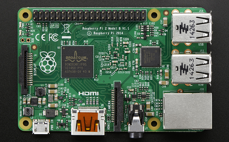
Oh, I looked for it on the pic and couldn’t find it.
half way between the power in and the HDMI connection and about 3 chips up from the bottom of the picture is U16
just incredible that some chips are non photon proof !
@stardreamer,
They are all. It is why they are encapsulated in black epoxy. Guess of what are made solar cells?
I mean none are (all silicon chips are sensitive to light).
more EMP than light sensitive
My laser pointer produces EMP?
You underestimate my laser pointer.
that would be one bad-a laser pointer :)
Light *is* electromagnetic radiation, you know…
Except for all the Uni dorm room hacks, where everything and the kitchen sink is hanging out in the open held by duct tape, it doesn’t seem like that big of a problem. I wonder if a black sharpie would solve the problem.
Probably not, tried it on an obnoxiously bright LED once and it only dimmed it a stop or two even after several coats.
Single Sideband or properly called Single Sideband Suppressed Carrier – e.g a 14000KHz carrier modulated by a 3KHz audio signal transmits a frequency equal to the carrier frequency +/- 3 KHz . For upper sideband 14003 KHz (USB) , for lower sideband 13997 KHz (LSB).
For double sideband both USB and LSB signals are transmitted.
For AM, the carrier, LSB and USB – (14000 + 13097 + 14003) are all transmitted as the carrier id needed at the receiver in order to recreate the original modulation.
On a SSB receiver only 13097 for LSB or 14003 for USB carry any intelligence as the carrier is reinserted by the receiver.
On AM modulated 100%, the carrier power transmitted accounts for 50% of the total and the sidebands 25% each.
On SSB the LSB or USB signal accounts for 100% of the transmitted power making SSB 4 times as efficient as AM.
Enter the new wave of Software Defined Radio (SDR) – less hardware complexity. Modes – AM, CW, SSB, FM, etc. – steep sided Filter settings, AGC, noise blanker etc. all determined by the software instead of by hardware designed for each function.
Tiny SDR http://www.qrz.lt/ly1gp/SDR/ is as simple as it can get.
What does THAT have to do with anything related to Raspberry Flash Syndrome?
posted in the wrong thread, and I’m leaving this here as a reminder to check what thread you’re posting in
RFS +1
I was really hoping for a photonic induction reset.
He’s too busy blowing up kitchen appliances these days.
+1
I want raspberry flames.
so, this simplifies even the most basic task of writing a blinky LED program, now all you have to do is write a program to turn a LED on, and make sure that LED is pointing at the U16 chip
Someone _has_ to do this! Please!
Sounds like the ultimate useless machine.
Just tried it. A standard 3mm LED just doesn’t put out enough light. I don’t have any of the blinding blues or whites on hand.
Looks like we found a way to do a simple software/hardware like reset: just connect a LED to the GPIO and shine it on U16.
“It’s worth mentioning that an LED flash would not cause this phenomenon to happen – it has to be a Xenon flash.”
http://www.neowin.net/news/a-camera-flash-will-make-the-raspberry-pi-2-freeze-and-reboot
From the distance where you are taking a photo, probably not. But a LED stuck close to the chip should be able to.
The LED probably doesn’t have the right wavelenght. The bandgap of the junction in the chip makes it sensitive to a somewhat narrow range, so that you might need e.g. ultraviolet light to trigger it.
A UV LED maybe ? 930nm, might.
I wonder if this is something we’re going to be seeing more of, as packages get smaller, logic voltages drop, and sourcing quality components gets trickier.
Does anyone know a searchable part # or the function of U16?
On Semiconductor NCP6343 buck
its a top quality part, nothing wrong with it
If nothing was wrong with it, this thread would not exist.
These components ARE NOT INTENDED to be used on a bare PCB with no casing. Hell, all PCBs really should be in a case of some kind. So complaining that your naked PCB misbehaves when you do something silly to it is really akin to claiming that your head is defective because it catastrophically fails when someone fires a shotgun at it.
“…when you do something silly…”
Define “you”. If you are talking about the designers of the Raspi I think you might have a point. They put a part into a situation it wasn’t designed for. If you are talking about Raspi customers.. I think that’s a different story. I think it was pretty obvious that the Raspi was intended to be used outside of a box. If they needed to chose a different component or add a coating or sticker or something.. well.. that is the Raspberry Pi Foundation’s mistake for not doing so.
That being said, mistakes do happen. They very well may have “gotten lucky” when they were testing and never saw this problem. I guess they and anyone else making dev boards (especially hobbyist ones) like the Raspi, Arduino, etc… can learn a lesson here. As part of the testing stages put the thing under a very bright strobe light and see what happens.
The chip is fine, despite Mr Bramage’s comment. The finished Pi is apparently not fine. But it’s a small problem that a teeny bit of tape will fix. So that’s good then.
It’s unlikely (not impossible) there’s anything wrong with a genuine On Semi part, but maybe a counterfeit part was substituted.
no, this is normal for this type of packaging. There is nothing wrong with the part, its designed for use INSIDE products, not on a face of celebrities chased by a band of paparazzi.
So a failure on the part of the engineers that designed it. For pity’s sake, a chip should be able to handle a bit of light!
would you rather have unnecessarily over engineered part, or a cheaper lighter smaller one?
@rasz_pl: How is designing a part to be reliable “unnecessarily over engineered”? I’d pay a few cents extra for a part I knew could handle exposure to normal operating environments. Any engineer who let that design hit the market is obviously an idiot. Maybe an educated idiot, but an idiot nonetheless.
@DainBramage: The normal operating environment is inside an enclosure, which will block out light. If you feel the need to place blame, it is squarely at the feet of the RPi2’s designers, who didn’t anticipate the issue and chose the wrong version of the IC.
I would say this is normal for the chip and works reliably. A lot of Pi cases are even clear so putting it in the case won’t fix the problem. Just avoid taking taking pictures with a flash.
It’s not even a flash ROM
It is development/evaluation board, it should work without enclosure. It is shipped without one. So it should reasonably work without one.
Who decided that the normal environment is inside an enclose? And by the way a transparent enclosure is an enclosure. The problem can be easyly solved by using a darker epoxy to cover the chip. The truth is that the engineers didn’t test how immune to light the IC was.
Is there something in the datasheet that says not to expose this part to light? Or are the designers supposed to know this package type is susceptible to this kind of problem?
A lightning-BUG
+1
If anyone else is wondrring?
Its circled herehttp://i.imgur.com/mAKtA7W.jpg
http://i.imgur.com/mAKtA7W.jpg
That’s impossible even for a computer…
;)
It’s not impossible. I used to bullseye womp rats in my T-16 back home, they’re not much bigger than two meters.
(c:
Many Bothans died to bring us this information.
FYI: http://www.silabs.com/Support%20Documents/TechnicalDocs/AN0878.pdf
“AN0878: Methods of Reducing Light Sensitivity in CSP Packages”
Very informative, thanks. A quick summary: “A CSP package is essentially a piece of bare silicon.” It goes on to describe an example CSP MCU, proven photosensitive, which “has an opaque black coating on the top of the package. This is actually the backside of the die.” Wow.
so it’s SHOCKING to you that chips are not covered with inches of lead?
Odroid C1 has a dedicated IR receiver diode, try again rpi2…
To get better blue sensitivity, CCDs fro astronomy are thinned and illuminated from the back side. Xenon flash is loaded with blue and UV light. If the flash tube is quartz (and most are) then the UV gets out easily. A flip chip die suggests this device is being illuminated from the back and would be more sensitive in the blue region.
I read that someone reproduced the failure with a green LASER. From a part manufacturing point of view, perhaps this part was never specified to be used in the light of day, but is meant for enclosed PSU’s like all the little wall wart 5V and 12V – and enclosed without even a green ‘ON’ LED anywhere near.
Bad component/package choice by someone who is not an industrial designer?
After reading AN0878 that [Tekkieneet] linked, you may be right about a bad choice. Though I don’t think your example of a green indicator LED would be an issue, it’s nowhere near as bright as a laser or flashlamp.
I’m surprised something as short as a flash used close can do this, unless there is latch-up, to which CMOS is susceptible. A lot of xenon flashes shut off early when used close to get the exposure right and the flash can be shorter than 0.0005 seconds. Funny business, this quantum electrodynamics.
Well, we now know that’s a switching power supply chip being affected. Suppose it registers that 500us of photonic energy not as a digital logic error or latch-up, but an analog one; such as an overvoltage at the output past safe limits. At which point it resets, then restarts, including any soft start time – which with the switchers I’m currently working with, constitutes the majority of time at 15ms. During which time the voltage on the output cap could drop enough to trigger another event, undervoltage reset on the MCU. I don’t know if it’s really happening this way, but it’s easy enough to imagine a scenario like this, so I can’t say I’m surprised.
Probably not a latchup problem but rather an analog one. The flash is probably dumping a bunch of charge in to or out of one of the integration caps in the switcher control loop. Nice low physical-energy state (controller integration cap) at the input of an amplifier that directly couples it to a high physical-energy state (the inductor current).
Anyone know if when the watchdog timer is set if it successfully reboots from this freeze?
http://youtu.be/LQo0fBzMO8Y?t=2m12s
May be automated laser tag bots for the HaD prize! The owner of the bot that left standing wins the game.
Use this to make a Schroedinger’s Pi. Use the same system as Schroedinger’s Cat but instead of releasing poison gas, have it trigger a Xenon flash.
With the Pi running but having no output visible, audible or otherwise detectable outside the box the Pi is in, you don’t know if at any given moment the Pi is alive or dead.
I would think that would work better than the whole cat thing. Since it has always sorta bothered me because I would think that the cat would act as its own observer. Course I also havn’t really bothered looking into the whole thing past the occasional anecdote that pops up from time to time.
One could use this for a nice watchdog mechanism. Optically decoupled reset function. But I guess only this batch is going to have this neat little bug.
Since we don’t know if the problem produces a safe reset, or causes stress to the chip, I wouldn’t rely on this *feature*. Fun though… but in the same league as zapping coin op machines with a piezo lighter.. don’t try with modern coin ops folks, it’ll land you in all sorts of bother }:~)
back in the 70’s/80’s when I was a game arcade tech, I wired up all our video game coin mechs with a 1uf ceramic capacitor to the slam switch.
That got my attention to the little pricks, I’d drag them to the door, take a polaroid to add to the wall of shame, never to be allowed in again list and kicked their sorry asses out onto the street.
What did that cap do? Can you explain more in I-know-only-what-you-tell-me way?
it lengthened the pulse from the electrostatic lighter thing so to kinda “simulate” a hard knock to the coin door.
the “slam” switch was there on video machines to prevent little pricks beating a free game out a machine
The 1uF cap would “filter” glitches…
Um, from what I read, the slam switch is supposed to *detect* any abnormalities, ie. “freeplayers”, so how making it less sensitive would be beneficial? Or did he do that on purpose so they were encouraged to slam the machines? It is still unclear to me.
If I remember right..You could trigger a freeplay by slapping the door hard enough. The slam switch is like a tilt on a pinball. Hit it hard enough to work and the slam switch would set off an alarm.
no video game EVER had free play! No alarm, it just reset the machine and cleared the number of plays, hi score and current score.
but, yes, it was kinda like a tilt switch, just a weight on a piece of spring steel with a contact.
Pinball machines had them as well, the tilt “switch” was a plumb bob looking thing that was suspended in a circular hole.
more like stretch the glitches so it looked like a hard knock
mainly the slam switch reset the machine, which was usually fairly “rowdy”, it gave me enough time to get there and put “foot to ass”, every now and then some cocky little so and so would try and put up a fight, hence the wall of shame polaroid!
the little creeps with electrostatic lighter guts would often try to “sell” free games to suckers!
When I was a pimply faced kid back in the 60’s I built one of Clive Sinclair’s designs – a regen receiver using a OC44 & OC71 germanium transistors. These were glass encapsulated devices with paint that peeled off easily. I had enclosed the radio in a transparent plastic soap container and took it with me to the India vs. Australia test match. That was when I discovered that the source of the unexplained whistles and pops – exposure to direct sunlight was throwing the regen first stage out of whirl!
Jacques1956 says:
“Who decided that the normal environment is inside an enclose?”
Yes indeed Jacques, why don’t you head down to your local electronics store and point out all of the consumer devices with exposed circuit boards.
calm down people… PRi 2 is just selfie alergic :D
Fyi, u16 is one of two chips that are bare silicon… it does not have a plastic case! The other is u8….
i think u8 is just a pack of clamping diodes for hdmi esd protection
Does the B+ have any analogous issues? (From reading they both have a more efficient power supply section compared to the earlier models.)
Woopsie.. I killed my Pi by flashing it twice.. lol
https://www.youtube.com/watch?v=IaCfs5Xb-EI shows at 7 minutes a possible reason for the crashing of the device