Hackers everywhere are having a lot of fun with SDR – as is obvious from the amount of related posts here on Hackaday. And why not, the hardware is cheap and easily available. There are all kinds of software tools you can use to dig in and explore, such as SDR# , Audacity, HDSDR and so on. [illias] has been following SDR projects for a while, which piqued his interest enough for him to start playing with it. He didn’t have any real project in mind so he focused on studying the methodology and the tools available for analyzing 433MHz RF transmission. He describes the process of using MATLAB to recover the transmissions being received by the SDR
He started off by studying the existing tools available to uncover the details of the protocol. The test rig uses an Arduino UNO with the rc-switch library to transmit via a common and inexpensive 433MHz module. SDR# is used to record the transmissions and Audacity allows [illias] to visualize the resulting .wav files. But the really interesting part is where he documents the signal analysis using MATLAB.
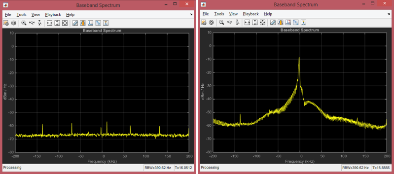
He used the RTL-SDR package in conjunction with the Communications System Toolbox to perform spectrum analysis, noise filtering and envelope extraction. MATLAB may not be the easiest to work with, nor the cheapest, but its powerful features and the fact that it can easily read data coming from the SDR makes it an interesting tool. For the full skinny on what this SDR thing is all about, check out Why you should care about Software Defined Radio.


Cool! Could the same have been done in Octave as well? Just wondering if Octave has similar libraries for signal processing.
Octave even has a MatLAB lib to make the code almost the same.
Use can even script it:
#!/usr/bin/octave -q
printf(“\nswoon… <3 we don't want to pay $12k per cluster node for FATlab");
That is vastly overcomplex for recovering OOK/ASK. Now, if it recovered FSK, I’d think it a bit more useful.
Please Old’un, be so kind and leave some perl code here that emulates a simple envelope and product detector and interfaces between a SDR (GNUradio perhaps?) and /dev/dsp.
I also wonder if some of this could have been done in GNURadio?
There is a slight development on the RTL-SDR which you can buy in kit-form or pre-assembled:
http://www.aliexpress.com/item/DIY-KIT-100-KHZ-to-1-7-GHz-all-band-radio-RTL-SDR-receiver-RTL2832-R820T/32272386214.html
(There’s a comment that no manual is supplied. For me the seller sent a link per AliExpress’ internal messaging system with assembly instructions. It has not yet arrived in the mail for me but I’ll surely post something of a verdict the next time SDR is mentioned on HaD.)
The RTL2838 only uses one half of its I/Q input, so this hack involves soldering a bit of wire to the unused port. This way you get all the ham bands without an up-converter. Since these are sub-VHF frequencies going over the bodged wire there are in fact not great difficulties to overcome with this approach.
There are by the way good reason to use GNU Radio for this kind of thing. It behaves very much like a visual programming language so it can be used to both learn about DSP and rapidly develop new things. Gnuradio uses FFTW, so the performance is pretty much guaranteed to be top-notch outside of hardware accelerators.
Aaaaand he paid for MATLAB and toolboxes. Yeah, right.
The home use and student editions are actually very reasonably priced (order of magnitude less than commercial).
His website says he is a student so he probably has access through the university.
€ 105 for matlab, €29 per toolbox. (Home edition) Not cheap, but I paid a hell of a lot more for WordPerfect and Word, once.
He did some cool work, but if the protocol was the target, then why not tap the base band before it modulates the transmitter.
Speaking of SDR with TV tuners…. is there a transmitter equivalent of the TV tuner?
The only economical solution I have found for XMIT is the HackRF. All other transceivers are high dollar.
the wb5rvz softrock series are a lot cheaper but they only cover 3 ham bands at most.
If you mean comparable in frequency ranges and such, HackRF and BladeRF are pretty much it.
If by “equivalent” you mean a dirt-cheap, mass-market device for another purpose which happens to be repurposable as a generic SDR with a little hacking, then I suppose a video card would count: AM, FM, or even DVB-T/NTSC/PAL.
(I wrote a long-winded ramble about VGA-based SDR, but realised I was drifting pretty far from a simple answer to your simple question, so I’m breaking it out into a reply to this post….)
I’ve actually given considerable thought, and a little experimentation, to the idea of using a VGA output for SDR. You get decent bandwidth (0 to pixelclock/2), which easily covers everything from DC to 6m (for cards that can drive 1920×1080@60Hz) or even 2m (for cards that can drive 2560×1600@60Hz) directly. For VHF/UHF and beyond, of course, you can use an upconverter — and the ridiculous bandwidth means you can completely cover 2m+1.25m, 70cm, 33cm, and 23cm, each with a single, fixed-offset upconverter. You may or may not be able to cover 2.3-2.31GHz and 2.39-2.45GHz with a single upconverter (you’d need a good video card and good filtering), and all bands above 13cm are definitely too wide.
Anyway, the bandwidth’s great, the resolution’s not bad (only 8 bits, but you can combine two channels for more dynamic range, either by attenuating and summing e.g. R+B/256, or simply multiply e.g. R*B), but the one big problem, as I see it, is the blanking. IIRC, when I did some experiments, I was able to get several video cards to run with 1 pixel of horizontal blanking and 1 line of vertical blanking, which is very good compared to real video timings, but not good enough to completely ignore.
One obvious solution is to pick timings such that these correspond to nulls in the signal — for instance, I was contemplating hellschreiber modes, and for ordinary feld-hell, the rule is 17.5 columns per second; thus one selects timings to generate 17.5 frames per second, and the vertical blanking lies within the feld-hell intercolumn blanking. (This also means we can use more lines of vertical blanking, if needed…) For the horizontal blanking, we can line it up with zero-crossings of the carrier, so we need only make the carrier frequency an integer (or even semi-integer) multiple of the horizontal frequency. Since the vertical timing requirement is generally stated to be +/- 0.1%, a good strategy is to first select a dot-clock and horizontal resolution to generate a horizontal frequency that is (1) a factor of the desired carrier and (2) greater than 17.5kHz, then choose the nearest vertical resolution (since we have at least 1000 lines, we’ll be no worse than +/-0.05%).
But there’s still a slight problem — VGA outputs range from 0 to 700mV, and blanking forces it to 0; we could generate an offset waveform centered about 350mV, but then the blanking becomes a glitch to -1 instead of 0! Every solution I could come up with either poses unreasonable requirements on the signal to be transmitted, or requires external hardware.
The solution I was pursuing at the time is to use 2 of VGA’s 3 channels as a differential output, giving us effectively 9 bits and 1.4V peak-to-peak, and blanking is now properly centered. (Of course the third channel may be attenuated and summed on either side of the differential output, to expand dynamic range.) This should work great if you can arrange your horizontal blanking to coincide with zero-crossings, which is straightforward for OOK or AM modes, and even some wierder things like MT-Hell, but it’s not clear to me that such an arrangement is even possible for FM/FSK/PSK or SSB modes, much less how to do it.
The other attractive option is to rig up a sample-and-hold circuit gated off the Hsync signal, so that the analog output remains unchanged during blanking — while this removes the requirement that blanking to coincide with zero-crossings, it does halve available bandwidth for a given pixel clock (from pixelclock/2 to pixelclock/4). Or better yet, but also more complicated, to sample and hold a separate channel, and substitute that channel during blanking — so the last pixel in each row might hold the current value in R, and the value to be output during blanking in G. (Extending this, one could replace the sample-and-hold with a delay line, and cover arbitrary blanking, if there was some reason not to reduce blanking to 1px.)
VGA FM Transmitter
http://bk.gnarf.org/creativity/vgasig/html/
Yeah, I thought that was a pretty cool demo with good explanations, which is why I linked it in my first post. :)
I though about it lately too just after reading about Raspee VGA666 module and new firmware enabling (hidden to that point, yay for broadcom closed source secret juices …) parallel video interface (raw RGB + H/V). So far there is no way to control timings of this interface, there is special parameters for custom HDMI timings
http://www.raspberrypi.org/forums/viewtopic.php?f=29&t=24679
hdmi_timings= <h_sync_polarity
, but there is a chance that:
1 Rpee foundation adds custom timing to this interface too, LadyAda from adafruit was very interested in it, maybe to sell cheap LVDS LCD screens for pee, (just need cheap serializer chip to mate ordinary laptop lcd with this interface)
2 Broadcom video rasterizer can be coerced into zero blanking
Precisely this i mean: “dirt-cheap, mass-market device for another purpose which happens to be repurposable as a generic SDR with a little hacking” thanks for the tip!
As cool as this is, I think the maker/hacker community would like to see this in an foss program such as octave, scilab, python, or gnuradio.
Shout out for Octave! It’s basically open source MATLAB
Google ‘gnu octave sdr’ and your first hit will say:
“Octave is the most popular analysis tool with GNU Radio, as the GNU Radio package includes its own set of scripts for reading and parsing output.”
does anyone know the signal range on one of those transmitters?
So he has the analytic signal (I&Q), then he throws away the quadrature part, only to re-create it with a Hilbert Transform to get the envelope.
He’s downconverted to DC already, so why not just get the “modulus” directly from I&Q via Pythagoras? Seems like extra work to me.
The RTL-SDR has I&Q inputs but only uses I. The Q port is unused.
Most communications is narrow band. Say 25 kHz. That is plenty for voice and pager signals. Having the signal digitized at baseband is the first step. The using any of your favorite software tools, you can determine the modulation scheme and decode the bits (1’s and 0’s). Once you have the physical layer decoded (i.e. have the 1010100 streams). you can then 1)
sync up the markers, and 2) decode the bits into symbols (make human readable).
I think they have FSK decoders already in software. Just a matter of using the right digital filter.
Shame that DRM (not the rights management, Digital Radio Mondiale) isn’t mainstream yet because the chips are essentially a cut down SDR set to tune 70-110 MHz.