[bhunting] lives right up against the Rockies, and for a while he’s wanted to measure the temperature variations against the inside of his house against the temperature swings outside. The sensible way to do this would be to put a few wireless temperature-logging probes around the house, and log all that data with a computer. A temperature sensor, microcontroller, wireless module, battery, case, and miscellaneous parts meant each node in the sensor grid would cost about $10. The other day, [bhunting] came across the exact same thing in the clearance bin of Walmart – $10 for a wireless temperature sensor, and the only thing he would have to do is reverse engineer the protocol.
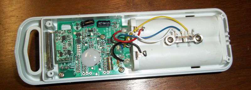
These wireless temperature sensors are exactly what you would expect for a cheap piece of Chinese electronics found in the clearance bin at Walmart. There’s a small radio operating at 433MHz, a temperature sensor, and a microcontroller under a blob of epoxy. The microcontroller and transmitter board in the temperature sensor were only attached by a ribbon cable, and each of the lines were labeled. After finding power and ground, [bhunting] took a scope to the wires that provided the data to the radio and took a look at it with a logic analyzer.
After a bit of work, [bhunting] was able to figure out how the temperature sensor sent data back to the base station, and with a bit of surgery to one of these base stations, he had a way to read the temperature data with an Arduino. From there, it’s just a data logging problem that’s easily solved with Excel, and [bhunting] has exactly what he originally wanted, thanks to a find in the Walmart clearance bin.


Now this would be handy if one were to read +1000C temps in a vacuum.
I am surprised he did nit just hook up a computer to try and read the data from the unit or make a processor emulate the system so he had better access instead of trying to decode using the O-scope screen.
Major kudos to him.
He used a logic analyzer. The scope was just to get a feel for the waveforms. Common reverse engineering techniques if you have the tools.
Reverse engineering implies probing the unknown. If I already knew everything about the circuit there would be no reason to reverse engineer it. Given that I did not know how the circuit worked, or what to expect for voltage levels or waveform timing, I started with the most robust, and often least informative, tools and worked my way to more specific, and less robust, tools, voltmeter -> oscope -> logic analyzer -> Arduino.
The voltmeter is safe to hundreds of volts but only gives limited information. The oscope will not handle the same voltage levels as the voltmeter but gives timing information. After using the oscope to find the bounds of the signal, levels and timing, I moved to a logic analyzer. The logic analyzer is only good for signals between -0.5 and 5.25 volts, not a lot of protection for hooking up to an unknown circuit.
After using the logic analyzer to visualize and decode the bit stream I hooked up an Arduino to automate the recording and decoding of the data.
As a side note an oscope is probably the greatest tool in your toolbox for reverse engineering unknown electronics. My cheap oscope scales from milli-volts to 10 volts per division and from nano-seconds to 10s of seconds, Four orders of magnitude in voltage and ten orders of magnitude in time. It is hard to find another tool with this much range for such a low cost.
Even when looking at a known digital signal, it is very helpful to use an oscilloscope when the circuit is misbehaving. Often the problem is not digital in nature. There could be two pins shorted, and the logical analyzer wouldn’t show anything out of the ordinary, while a scope will quickly show voltages at unexpected levels.
“the temperature variations against the inside of his hour against the temperature swings outside”
Wow, two in a row, Brian are you out of coffee this morning?
Actually, yes.
Friends, Don’t Let Friends Shop at w-wart….
Having this information in a computer can be useful. When the temperature dips outside, you can have the heating come on in anticipation of that. You can also do a host of other things.
I use a manual process to do something similar to save on electricity. In the winter, I watch for when the outside temperature is peaking, usually in early afternoon. Then I run my heat pump to warm the house up, turning on the ceiling fans so that heat spreads and soaks into everything. Then as the temperature drops, I turn my heat pump off and coast on that stored heat until the next day. It works quite well.
That’s taking advantage of the fact that a heat pump will be much more efficient moving heat from an outside temperature of 45 degrees than from 25 degrees. But once it’s stored inside my house, that more easily obtained heat has the same value in keeping the house comfortable.
In the summer, you can do the opposite, taking advantage of cooler outside temperatures at night to make discharging heat from the house less costly.
This is along the lines of what I am hoping to achieve long term. I have hot water heat and there is a significant time delay when changing the interior temperature. I am hoping to create a model of the relationship between the change in exterior and interior temperature and better predict the interior heating needs and timing.
may be info here helps to understand protocol
http://www.instructables.com/id/Wireless-power-outlets-for-home-automation-using-A/
I have found in the bargain bin at Lidl for the same price something very similar but with a DCF77 time receiver, also on a separate PCB with a little ferrite rod aerial in the base station. Output from the time receiver is the demodulated raw DCF77 code, 3V signalling. Can be handy to salvage if you ever need accurate time keeping on something that you want to run for years off batteries.