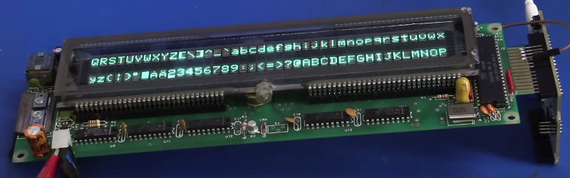
[Dave Jones] got his hands on a really wide, 2-row Vacuum Fluorescent Display. We’ve come across these units in old equipment before and you can get them from the usual sources, both new and used, but you need to know how to drive them. This recent installment of the EEVblog reverse engineers this VFD.
The function of these displays is pretty easy to understand, and [Dave] covers that early in the video after the break. There is a cathode wire and phosphorescent coated anodes. When current is applied the anodes glow. To add control of which anodes are glowing a mesh grid is placed between the anodes and the cathode wire. Applying negative potential to the grid prevents the electrons from traveling to the anode so that area will not be lit.
Now driving this low-level stuff is not easy, but rest assured that most VFDs you find are going to have a driver attached to them. The reverse engineering is to figure out the protocol used to control that driver. On this board there is a 2-pin connector with a big electrolytic filtering cap which is a dead giveaway for power rails. Looking at the on-board processor which connects directly he ascertains that the input will be 5V regulated since this is what that chip will expect. Connecting his bench supply yields a blinking cursor! [Dave] goes on to pump parallel data and test out the control pins all using an Arduino. He finds success, sharing many great reverse engineering tips along the way.
We often call this type of thing a dark art, but that’s really just because there aren’t a lot of people who feel totally comfortable giving it a try. We think that needs to change, so follow this example and also go look at [Ben Heckendorn’s] recent LCD reverse engineering, then grab some equipment and give it a try for yourself. We want to hear about your accomplishments!
[Thanks Indrora]


Anybody else get there hopes up only to find a hum drum Vacuum Fluorescent Display not a Variable Frequency Drive?
Yes. I was super excited.
Yup.
Curse you HaD and your lack of “edit”.
Yep. We use a ton of both types of vfd’s at work and I was really hoping to learn about the variable frequency drives. Oh well.
“We often call this type of thing a dark art,” Sussing out a luminous device is a dark art. Ho ho. Ha ha.
This must be VFD from POS customer display. They are usable, other VFDs are usually custom displays for VCRs and CD players, driven by all-in-one chip and quite unusable for any DIY purpose.
You can make an amplifier from one.
Is there link or something more so you can elaborate on that ?
https://www.youtube.com/watch?v=LEAhRayjNS0
Also try “vfd amplifier” in google search, it finds some more links.
actually the front panel from a car radio is an all-in-one Front Panel Driver with a two-way data path for scanning buttons and driving the VFD. and then if all you have is a bare VFD panel ( https://dl.dropboxusercontent.com/u/33593534/projects/VFD/IMG_2449.JPG ), you’ll have to visually find the pin and grid connections with a bright, non-glaring light ( https://dl.dropboxusercontent.com/u/33593534/projects/VFD/IMG_2474.JPG )
Dave is awesome!
Dave is the god of electronics.
Love vfd
I just wish these things lasted longer. They lose half their brightness after only 1000 hours of operation. Car makers still like them because they are a cheap display that can handle -40degF to 140degF temperatures the inside of a car can experience.
You can up the filament voltage a bit to compensate for the display dimming with age. I did that to the VFD in my Chrysler’s radio that was so dim on the highest brightness after 15 years of almost constant use, it was impossible to read. Eventually that will fail too, but if you have no option of replacement… ¯\_(ツ)_/¯
The only thing that gets “used up” is the filament, so you can start of running them a little cooler, too.
No, the filament only gets used up if you run the current too high. The electroluminescent phosphor chemically changes over time due to electron bombardment and it’s luminosity drops over time.
Which is easily seen, as dimming is not uniform over the display area but most on the most used segments.
I have a radio with a VFD that lost pretty much all of it’s brightness after the first year or so. Hopefully this video will give me a better of idea of where to start troubleshooting.
If anyone has any tips I’d love to hear them.
I am looking for example code for this kind of hack. Any ideas?? Thanks