Ever the enterprising hacker and discerning tool aficionado, [Chris] knows the importance of “feel”. As a general rule, cheap tools will shake in your hand because the motors are not well-balanced. He wanted a way to quantify said feel on the cheap, and made a video describing how he was able to determine the damping of a drill using a few items most people have lying around: an earbud, a neodymium magnet, scrap steel, and Audacity.
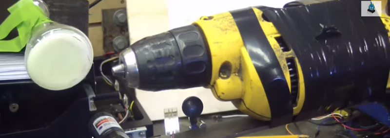
He’s affixed the body of the drill to a cantilevered piece of scrap steel secured in a vise. The neodymium magnet stuck to the steel interrupts the magnetic field in the earbud, which is held in place with a third hand tool. [Chris] taped the drill’s trigger down and controls its speed a variac. First, [Chris] finds the natural frequency of the system using Audacity’s plot spectrum, and then gets the drill to run at the same speed to induce wobbling at different nodes. As he explains, one need not even use software to show the vibration nodes—a laser attached to the system and aimed at a phosphorescent target will plot the sine wave.
Just for fun, he severely unbalances the drill to find the frequencies at which the system will shake itself apart. Check it out after the break.


I had to look it up to confirm, but this is the same basic principals that a tire balancing machine uses to balance a car tire. A computer monitors the deflection of the spindle shaft and handles all the calculations for weight size and placement.
Computer? Ha! I could it with a 555! B^)
The old dynamic wheel balancer (I worked at a Ford dealership in 1976, and their wheel balancer was a few years old) didn’t use a computer.
First the wheel tech chalked an “X” on the tire sidewall next to the valve stem.
The car was jacked up and the axle placed on a special jack stand (it had a vibration sensor in it).
Then an electric motor spun the tire. Vibration would trigger a strobe light to flash on the tire. At the right speed the “X” would appear stationary on the moving tire. The wheel tech noted the position of the “X” and after stopping the spinning would place a wheel weight at the “12 o’clock” position from where they noted the ‘X” to be. They would spin up the tire several times to get a more accurate “reading” each iteration.
We used to do big truck with that very system. Balanced everything, brake drum and all
Well, steel spring. DC motor that is next to steel spring turning fields on and off. Chuck jaws in unknown position. Not sure who is driving what except with the way off balance run. I missed the how to balance your tool part.
It does seem like even if the tool is off balance, the resonance spike is going to be at the natural resonance of the cantilever and not the motor. You can see this when he sweeps the frequency by increasing the RPM. The motor’s off balance-ness doesn’t change with RPM, but the induced vibration in the cantilever will. Also, mock jacking off? Still, there are some decent ideas in the video, like using earbuds and audacity. By changing the resonance of the cantilever (different weights, length and dampening), you might be able to draw some meaningful conclusions about the motor itself.
I agree. It’s easy to tell if it is out of balance. Now if it told at what angle and how much, that would be something. All this tells me is not to run your drill at the natural frequency.
Hackaday is staring to look like my RSS feed, only a couple of days later. Not a bad thing persee.