April Fools’ Day may have passed, but we really had to check the calendar on this hack. [Damian Peckett] has implemented an Apple ][, its 6502 processor, and a cassette port, all on an Arduino Uno. If that wasn’t enough, he also uses a PS/2 keyboard for input and outputs analog VGA. [Damian] is doing all this with very few additional components. A couple of resistors, a capacitor and some very clever hacking were all [Damian] needed to convince an Arduino Uno that it was an Apple.
Making all this work boiled down to a case of resource management. The original Apple ][ had 4KB of RAM and 8KB of ROM. The ATmega328 has only 2KB of RAM, but 32KB of Flash. The only way to make this hack work would be to keep as much of the emulation and other routines in Flash, using as little RAM as possible.
The core of this hack starts with the MOS 6502, the processor used in the Apple. [Damian] wrote a simple assembler which translates the 6502 opcodes and address modes to instructions which can be executed by the Arduino’s ATmega328. To keep everything in ROM and make the emulator portable, [Damian] used two large switch statements. One for address modes, and a 352 line switch statement for the opcodes themselves.
A CPU alone is not an Apple though. [Damian] still needed input, output, and the ROM which made the Apple so special. Input was through a PS/2 keyboard. The PS/2 synchronous serial clock is easy to interface with an Arduino. Output was through a custom VGA implementation, which is a hack all its own. [Damian] used the lowly ATmega16u2 to generate the video timing. The 16u2 is normally used as the Arduino Uno’s USB interface. The only external hardware needed is a single 120 ohm resistor.
The original Apples had cassette and speaker interfaces. So does this emulated Apple. [Woz’s] original cassette and speaker interface accurate loops to generate and measure frequencies. One of the trade-offs [Damian] accepted in his 6502 was cycle accuracy, so he couldn’t use the original routines. Not a problem though, as he was able to write simple functions to replace these routines and drop them in place of the Apple’s own ROM calls.
The Apple ][ ROM itself is handled as one giant character array. This includes the system monitor, Mini-Assembler, Sweet-16, and [Woz’s] own Integer Basic. [Damian] caps off this incredible project by booting his new computer, loading a Mandelbrot set program from cassette -or in this case an audio file stored on his cell phone, and running it. The well-known fractal is displayed in all its glory on a modern LCD monitor, driven by a microcontroller, emulating a computer from nearly 40 years ago.
Thanks for the tip [Bill]!
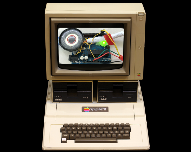
Apple II Image by RAMA, [CC BY-SA 2.0], via Wikimedia Commons


With it running in flash, how long do you think the chip would last? Great step towards running Oregon trail? Maybe Atari, or 2 arduinos running nes emulation(one for ppu and other for cpu). Awesome work!
No unusual FLASH wear issues that I can see here. The emulator and Apple II ROM is in FLASH, and it doesn’t need to be reflashed unless you update them.
Any Apple II program you load, and variables, are stored in RAM. If there were much more RAM available, it would have been possible to perform JIT compilation – converting every 6502 opcode to its AVR equivalents only once, then running the translated AVR code from RAM. Instead, every 6502 opcode must be translated each time it’s executed. Even then, this has less available RAM than the Apple II it emulates – but still enough to run simple programs.
While that’d be possible to do the translation with more ram it wouldn’t be possible to run it from RAM due to the way AVRs are architected. Because it’s a modified Harvard architecture you can’t actually run code from RAM in any way. You have to write it to flash in order to get it to execute.
The solution is that of Dan64, an emulator that run code that can be be in RAM or SPI RAM like it is the case with DAN64
My bad, I’m a PIC guy. I thought AVR could execute from RAM, but I must be thinking of ARM.
Some 8051 versions can execute from RAM too, I think.
Oregon Trail or it didn’t happen :)
http://www.black-ogre.com/blackogreonline/wp-content/uploads/2012/01/he_died_of_dysentery_poster-rb3a5121f7fb745308409739a0cca55ec_i5h_400.jpg
I prefer Wings of Fury or Rescue Raiders.
SnakeBite!
Add an SPI SRAM like [Juan]’s Dan64 for more memory, although accessing external RAM would slow down the emulation.
I was curious to see how he realized VGA on an AVR until I read the page linked. It is not VGA. VGA specification is 640×640 pixels 16 colors. What he have done here is black and white with sync signals compatible with a VGA monitor. The resolution is only 150×90. R,G,B inputs on the monitor are shorted together.
He would have got a better resolution generating a NTSC progressive scan for input to a TV. There is still NTSC composite input on modern TV in the form of GREEN RCA jack of the YPbPr input
http://en.wikipedia.org/wiki/YPbPr
correction: VGA spec is 640×480 16 colors.
Pedantically, VGA is an analog standard, so even on the original hardware getting ≈18bpp color only required a little trickiness. (e.g. use the 360×480 tweak mode, and group three vertical pixels into successive rows of RGB. If you think that’s cheating, you can still do simple raster effects and get to 735 colors onscreen simultaneously).
Let’s just say “Horizontal: 320/360/640/720 pixels, Vertical: 200/240/350/400/480 scanlines, arbitrary colors”.
VGA originally referred to IBM’s standard, but has come to mean any monitor/video card with the standard 15 pin high density D-sub connector and signals that go along with it. (wikipedia agrees with me on this one).
I still say that the pulling this off using the ATmega16u2 “co processor” chip on the UNO is an impressive hack.
Wonder if Woz is pissed somebody got it down to fewer chips than him :-)
Ok… wouldn’t it just be easier to figure out what you CAN’T do with an AVR???
Is the RAM enough, i mean if its a little bit more mabye it can perform faster, because its a bit low. But this is an awesome creation, simple and complex, but it could be made better, one of a kind.
The Arduino Uno can be powered via USB connection or with the External power supply.The power source selected automatically.