About a year ago, [Nick Johnson] over at Arachnid Labs sent a tip in about Re:load Pro, his digital constant current load design. [Nick] was running a crowdfunding campaign, which always makes me think twice about posting. However in this case, I had no qualms writing a feature here on the blog (and backing the campaign with my own cash). Re:load Pro is actually [Nick’s] third generation current load. Having purchased and used the original Re:load, I knew [Nick] was capable of fulfilling all the promises in the campaign. Turns out I was right – [Nick] and the Arachnid Labs team had a very successful crowdfunding campaign. All the kickstarter backers have been enjoying their units for months now. When it came time to stock up the Hackaday Store, the Re:load Pro was a no-brainer.
What does one need a digital constant current load for? Plenty of jobs could benefit from it! From testing batteries to verifying power supplies, to tests of many driver circuits, a digital load is a great tool to have in your arsenal.
Like many electronic devices, our first step with the Re:load Pro was to upgrade the firmware. Since the Re:load Pro is operated by a Cypress Semiconductor PSOC 4, firmware updates are handled by the cyflash python package. For now this means heading to the command line and installing pip and cyflash. Those who aren’t familiar with a command line prompt will find a step by step guide on the firmware update page.
I should note that the Re:load Pro is powered by the USB input. I connected it up to my lab PC, which had no problem supplying the necessary power.
Calibration
The next step is calibrating the Re:load Pro. This requires an adjustable power supply capable of supplying at least 10 volts at 2amps, a decent multimeter, and of course some test leads. If you don’t have a reliable adjustable supply ask around; it should be easy to find someone who does.
The calibration is performed in three steps – first with nothing connected to the Re:load Pro. Then a power supply set to approximately 9.99 volts is connected. The voltage displayed on the Re:load Pro is tweaked with the rotary encoder to display the same value as that of the power supply. My power supply has a rather cheap internal voltmeter, so I used a multimeter in parallel with the setup. With voltage done, the Re:load Pro will draw 2 amps from the power supply. You need to adjust the current displayed on the Re:load Pro such that it matches the voltage displayed on your power supply current meter. Again, since my supply doesn’t have the most accurate meter, I used a multimeter – this time in series with the Re:load and the power supply.
Taking Measurements
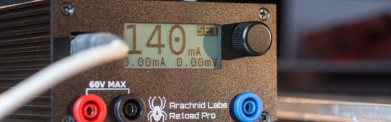
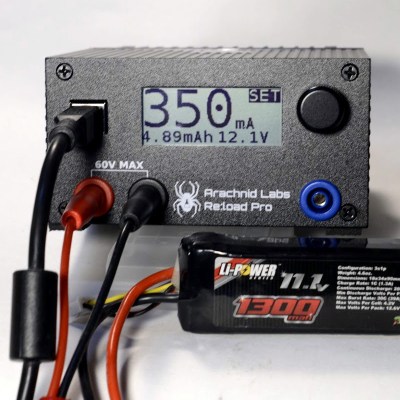 With all the preliminary work done, it’s time to make some measurements! Re:load pro has a simple user interface. everything is accessed with the rotary encoder on the front panel. Turn the dial to your desired value, and press to select. In my case, I wanted to check the voltage drop of a LiPo battery under various loads. I simply hooked up the battery and dialed 350ma on the encoder. The Re:load Pro showed me that the battery was holding at 12.1 volts, and a display on the lower left side showed me how many milli amp hours I had pulled from the battery.
The Re:load Pro’s USB connector isn’t just for power. It will show up on your PC as a serial device. Just open your favorite terminal emulator, set the port to 115200 baud 8/N/1, and you’re good to go. The Re:load Pro uses a simple text based command/response protocol, all the commands are outlined on the Arachnid labs page.
Conclusion:
Re:load Pro is one of the first of new breed of open source tools. Like the closed source Rigol Oscilloscope, it replaces tools which cost several times more. [Nick] and Arachnid Labs aren’t just resting on their success though – they’ve just finished up a kickstarter for their latest open source tool. Tsunami is an open source signal generator based upon the Arduino platform. Tools enable projects, and open source tools are the best way to push the entire ecosystem forward.
Editor’s Note: We are reviving the concept of “Reviews” on Hackaday. These were pioneered long long ago by Hackaday Alum [Ian Lesnet] with his post on smart tweezers but little has been done since. We see a lot of tools, parts, raw materials, and equipment flow through our inbox. We plan to post reviews as a new Hackaday Column. These reviews are not paid placement, they are chosen by editors and writers based on our own interest. This particular example is available in the Hackaday Store and we started with it because we already have the hardware in-hand. However, we will be reviewing items we do not sell and have already put out requests for review units. If you know of something you think worthy of a review, please let us know by submitting it to the tips line. Thanks!
-Mike Szczys, Managing Editor


Nice to see this as open source. I’m interested in something on the order of 1kw.
Uh, yeah, we’re going to need some details on that.
I mean, they can be made, with careful* paralleling of mosfets…and watercooling. I’ve built a 1.8 kW unit for a consulting project once — was an interesting challenge. Fun for curving car batteries, too.
Dissipating the power in your MOSFET as heat inside a box isn’t too scalable. There are other ways of solving the problem if you don’t require fast transient response or go below a fraction of a volt.
Shameless promotion: I am building a dual channel battery charger / analyzer that uses SEPIC buck/boost converters for charging/discharging batteries. Because it is under firmware control, you can do constant current/power all you want. For discharging, I swapped the connections so that the buck/boost converter uses the battery as power source and let you use an *external* load. Keeping the heat dissipation outside of your power and control electronics reduces the cooling requirement and make your electronic more robust. The buck/boost converter would adjust the output voltage for the required power/current drawn at the battery side.
Mine isn’t rated for 1kW, but at least I know it is more scalable than a brute force linear design.
I had a friend into amateur radio, we made a dummy load capable of handling a 100 watts. We wired a bunch of beefy resistors in parallel, and put them in a paint can full of mineral oil. Something like that might work if you really need to handle a kilowatt. Although it might cover you in hot oil, and possibly burn your house down.
You are describing something very similar to the old Heathkit Cantenna.
1 kW isn’t that bad. That’s a small electric hot plate. It’s easier to dissipate the heat, when the element is really hot. Black body radiative power goes up with 4th degree of temperature, so a small red hot element can dissipate a lot better than a bucket full of boiling mineral oil.
Glad to see that reviews will be making a comeback.
2 minor points. The display has no margin, digits at edge are cut off. The positive terminal is left of the negative. Right is increase, left is decrease. So the negative should be left of zero, positive to the right of zero. For a product these are not minor.
I usually just use a car headlight for a low voltage load, or get out resistors.
If you look at their actual product page –
https://www.tindie.com/products/arachnidlabs/reload-pro/
you will see a different screen, in which there is a margin so text does not appear to be cut off – and the knob is different too.
Not sure about the right increase left decrease thing though. If you look through fluke meters their negative and positive positions are not even consistent within the brand. Some meters are set up negative-positive some are set up positive-negative thought I think negative would typically be called common on their meters. Not that fluke is the end all be all and finality to the question at hand, but I think they have a proven track record of successful products.
I have a reload pro and the screen can be setup the way you like it. That said: The Menu/Layout is kinda ugly and not well thought thru. That said, is assured me that arachnid labs is a hardware guy, not a designer.
There is no such standard for the location of the terminals. I just cocked my head to see what you were on about and found my bench power supply goes + – GND + – + -, my bench multimeter voltage input is + – except vertical and my multimeter voltage input is – +.
Now if the colours were wrong that would be something to worry about.
HP/Agilent bench power supplies universally seem to put positive on the left.
Most Rigols are positive = left, but some are flipped! (And some are vertical.)
Mastech and many similar cheap bench supplies are positive = right.
I’m sure there has been a human factors study on power terminal position, but I don’t think “right increase, left decrease” is it.
Of bigger concern: what is that blue jack off in limbo to the right? It’s not mentioned in the manual on GitHub. Chassis ground is universally green or black. And why isn’t it on .75″ centers with the rest of the jacks?
Reviews are good. Never ending contests are bad.
I wonder if it can pull constant power as well, so when you’re simulating a battery drain it would draw more current as voltage drops. I’m not an EE but I think this would be a better simulation of how a constant voltage power supply would drain a battery. Maybe as simple as writing some custom code for it.
That would be useful. The professional electronic loads I’ve used can do constant resistance (useful for testing switchmode power supplies which can have trouble starting up into constant current loads) and constant voltage (useful for testing current-controlled voltage sources such as solar cells, or for roughly emulating LED loads) in addition to constant current. Constant power is a little more fun since at very low inputs – such as when a switchmode supply is starting up – the desired current approaches infinity. But it’s simple enough to deal with that by defining minimums and maximums in the firmware. It’s all just firmware changes, and simple enough to do if you already know the voltage and the current across the load element.
Thanks for the review! As a guy with a limited amount of electronics equipment, it’s great to see what I should consider investing in. Especially when it has open source elements!
Bit of a necropost, but missed this review when it was posted. Personally I’m not that happy with my Re:load Pro, and not all are due to it being a “monday morning work”, there are many bad design decisions and “oops”, not to mention annoying things, glitchy and crashing, and I have had to spend some time fixing mine before it was even usable.
I was in the kickstarter and have a V1.0. Quite a few bad soldering spots, which is bad when the +5V from the USB accually bridges the gap and is connected to groundplane. Didnt work until I fixed that. Its bad missing insulation basically always is needed on TO-220 to stop having the heatsink being electric (although nice to send insulation kits out for those requesting it, I had already fixed that when I opened it to check why it didnt start and resolder). The PCB trace going from minus connector on PCB to R16 (shunt resistor) was 1mm wide. And its also bad that the shield on the USB connector touches frontpanel (casing again), and same applies to the wheel, touching the casing. The PCB earthplane reach too far out on both sides and can if the coating gets scraped/damaged touch the sides of the aluminium casning, and shorting from side to side. Firmware V1.3 was way less annoying than V1.9 atleast for me (perticulary the calibration, which I have had to do way to many times).
Lost count on how many times i have had to factory reset it and recalibrate it (30+). My Re:load was really glitchy, crashed and rebooted, until I spent time fixing things like this. Still have to do a factory reset/recalibrate from time to time and crash/resets a lot of times but is better and atleast usable.
Is Arachnid Labs still in business?
I have one of their Re:load Pro’s and want to get the fw updated but it doesn’t seem to work per their upgrade instructions.
Thanks for any help provided.