A rubidium standard, or rubidium atomic clock, is a high accuracy frequency and time standard, usually accurate to within a few parts in 1011. This is still several orders of magnitude less than some of the more accurate standards – for example the NIST-F1 has an uncertainty of 5×10-16 (It is expected to neither gain nor lose a second in nearly 100 million years) and the more recent NIST-F2 has an uncertainty of 1×10-16 (It is expected to neither gain nor lose a second in nearly 300 million years). But the Rb standard is comparatively inexpensive, compact, and widely used in TV stations, Mobile phone base stations and GPS systems and is considered as a secondary standard.
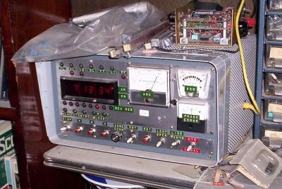
[Max Carter] recently came into possession of just such a unit – a Lucent RFG-M-RB that was earlier in use at a mobile phone base station for many years. Obviously, he was interested in finding out if it was really as accurate as it was supposed to be, and built a broadcast-frequency based precision frequency comparator which used a stepper motor to characterise drift.
Compare with WWVB Broadcast
The obvious way of checking would be to use another source with a higher accuracy, such as a caesium clock and do a phase comparison. Since that was not possible, he decided to use NIST’s time/frequency service, broadcasting on 60 kHz – WWVB. He did this because almost 30 years ago, he had built a receiver for WWVB which had since been running continuously in a corner of his shop, with only a minor adjustment since it was built.
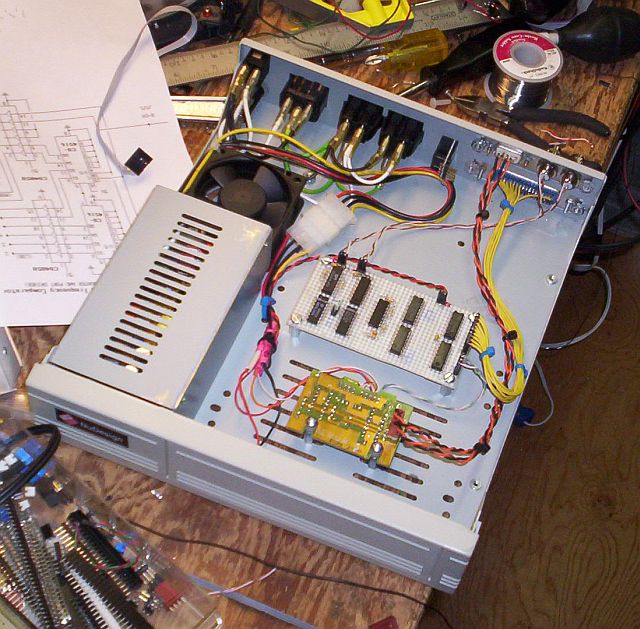
His idea was to count and accumulate the phase ‘slips’ generated by comparing the output of the WWVB receiver with the output of the Rb standard using a digital phase comparator. The accuracy of the standard would be calculated as the derivative of N (number of slips) over time. The circuit is a quadrature mixer: it subtracts the frequency of one input from the other and outputs the difference frequency. The phase information is conveyed in the duty cycle of the pulses coming from the two phase comparators. The pulses are integrated and converted to digital logic level by low-pass filter/Schmitt trigger circuits. The quadrature-phased outputs are connected to the stepper motor driver which converts logic level inputs to bi-directional currents in the motor windings. The logic circuit is bread-boarded and along with the motor driver, housed in a computer hard drive enclosure which already had the power supply available.
Taking the Measurements
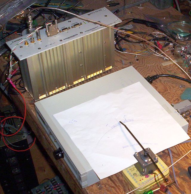
To check if it worked as the theory predicted, he first characterised a TCXO. The crystal standard was operated for about 2.5 hours (9000 seconds). In that time the pointer moved 90 degrees clockwise. Since it takes 400 steps for a complete revolution, 90 degrees represents 100 steps. Each cycle of “slip” at 1 MHz (the frequency at which the comparison is made) generates one step pulse. So, to characterize the standard under test, one would count the pulses (with the stepper, equipped with a hot glued cable tie pointer), multiply by 1/1000000 and divide by the elapsed seconds. The number of steps in this case was +100 and elapsed time was 9000 seconds. The calculation would be 100-6 / 9000 = 1.1×10⁻⁸. This was the error factor of the TCXO over the elapsed time.
Next, it was time to test the Rb standard. He ran the test for 44 hours and accumulated 7 steps in the counterclockwise (negative) direction. The frequency error factor calculates to -4.42×10⁻¹¹. Long-term ageing rate specifications for rubidium standards are usually in the range of ±5×10-11 per year.
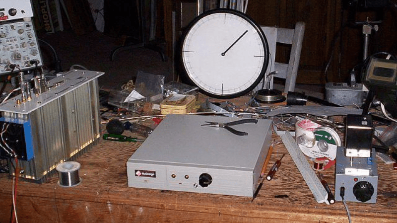
He later fixed the stepper motor inside an old analog clock case and attached a pointer to it. He also built an add-on circuit with 5 LED’s as outputs that functioned as a sort of a LEDscope (synchroscope), visually indicating if the standard was faster or slower than the reference. Finally, he also built a computer interface to log long term frequency data to a computer.
Even if you don’t have a Rb standard, [Max]’s system can be extremely useful in verifying, and adjusting if required, the frequency of other sources. The video after the break shows 1 MHz from the WWVB receiver compared to 0.999960 MHz from a signal generator. The difference frequency is -40 Hz and the stepper is turning counter-clockwise (at 1/10 revolution per second).
Thanks, [Chris Hemingway] for sending in this tip.


I’ve just skimmed the article but it looks interesting enough to bookmark and come back to read when I have more time.
the comparator looks simple enough so it does not look like its too hard to build. I have an rb box from ebay that I have calibrated to 10mhz via a friend’s gps-DO standard and its worth knowing that we did have to over-write the eeprom value for the cal constant to get it to agree with his 10mhz standard (I trust his, not the ebay box). but I don’t know the long-term stability of my box and it would be nice to be able to track that.
I’m most impressed that he actually built Don Lancaster’s WWVB receiver design from 1973.
http://www.tinaja.com/glib/WWVBexps.pdf
(and even more impressed to learn that Don is still at it after more than 50 years. Amazing guy.)
You don’t need to be a horologist to find this very cool. But I happen to be one, and I do!
Not the sort of thing I’d be doing- ever, but I know some high end companies who have
made world time atomic clocks that this technique could be used to certify, perhaps. Saw a Patek
atomic clock once- one of supposedly two made, can’t say where I saw it- it was in for repair.
It would be fun to have been able to test the standard using this method.
I vote for more atomic clock projects on HaD this is seriously cool stuff
More clock projects in general!
I’ve got photos of the horology museum in La Chaux de Fonds, Switzerland if anyone is interested.. :)
How would one go about upconverting an accurate time standard from about 60kHz to UHF or below and retransmitting it in low power?
Mix with a clean signal in the desired frequency range (say you want to transmit around 144 Mhz, provide a local oscillator of 144mhz, combine with 60khz signal, you get 144.06 mhz). Pass that to an amplifier, then to an antenna. But first, get your ham license ;)
In this way you will not benefit from the high accuracy 60 kHz source.
What is needed is a vco which is phase locked to the Rb source, this will take care of the frequency drift and is the easy part. Probably he needs low phase noise and it is as hard as low noise he wants to go.
Might be very hard to phrase lock for such a low frequency to a very high frequency without adding in a lot of jitters. In some of the ARM chips, you can only frequency lock a watch crystal vs a phrase lock from a few MHz crystal to generate the main clock. (FLL vs PLL)
A man with one clock knows the time… a man with two, doesn’t….