[Quinn Dunki] has been hard at work building a Teddy Top – an Apple IIc Plus modified for a road warrior. It has a 3.5 inch disk drive, runs at a blistering four megahertz, and has a beautiful integrated color LCD. It would be a shame to have such a great machine and no way to play games as they were intended, so [Quinn] set about building a game pad for her lovable Apple II.
The Apple II joystick port isn’t as simple as an Atari or Commodore joystick port. Where the bog-standard Atari joystick is basically just a bunch of switches connected to pins, the Apple II joystick is analog. Weird, and even weirder is the value of the pots in these joysticks: 150kΩ. Somehow or another, nobody makes pots in this value any more. Luckily the hardware in these joysticks is well documented, and shoehorning in modern components isn’t that bad.
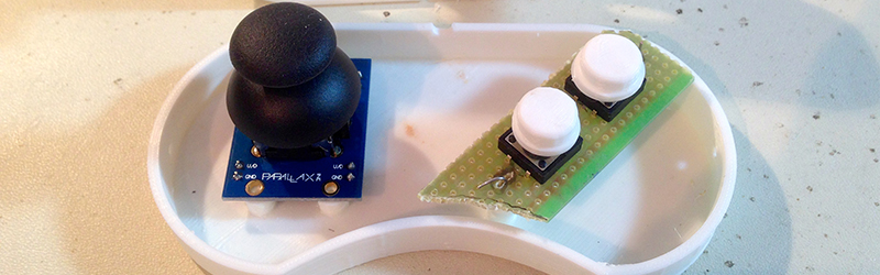
The Apple joystick has a bit of circuitry – a 556 timer chip that reads the values of each pot and converts that into a stream of 0s and 1s for the Apple. The joystick [Quinn] found for her game pad is an analog thumb stick on a neat breakout board manufactured by Parallax. This analog joystick has 10kΩ pots in it, and that just won’t work with the 556 timer chip. However, since this is just resistors and a 556 chip, adjusting some of the values on the original schematics does the trick. [Quinn] added a few capacitors to her circuit, and everything worked beautifully.
With the electronics down, she turned her attention to the case for her Apple II road warrior enclosure. She recently picked up a 3D printer, which means she’s new to 3D printing. After spending a few hours designing a controller in 123D Design, she sent the files over to the printer. Warping happened. She tried an ABS slurry. The part was stuck to the bed. It took a few tries (purple glue sticks are awesome, [Quinn]), but she eventually got her plastic enclosure printed out, and the circuitry installed. The result is a portable computer, with a custom controller, playing Lode Runner. Can’t beat that.


556? She could’ve used a couple of 555’s… Oh, right. (c:
Just kidding. Love her work.
BTW, what happened to Veronica?
no those are inside the apple II. its kind of like the ibm joystick interface. you write a logic 1 somewhere to charge a capacitor, and set a timer. then you discharge that capacitor through the pot. when the voltage drops below the low logic threshold, it triggers an interrupt and then you read the timer in your isr to get your axis value. this makes the whole thing really anal about pot value, hence the hack.
What [Brian] wrote:
“The Apple joystick has a bit of circuitry – a 556 timer chip…”
Falsely gives the impression the 556 is in the joystick. Fooled me too. I was curious to see how [Quinn] bypassed the 556 power rails, because with a 200mA shoot-through transient every time it switches output state, the two timers can easily interfere with each other. Wasn’t until I looked for the 556 in [Quinn]’s joystick, and found none, before I realized what the deal was. It would be more accurate to say the “Apple joystick PORT has… a 556”.
And now that [Lord Nothing] mentions it, I recall working on an old PC and seeing a 558 on a dual joystick interface. Recognizing the part and wondering what it was doing there, I looked up how the joystick interface worked. Feels like an ancient memory now!
I always thought the joystick of Apple II is odd. Games often need to do its own centering as every joystick would have a slightly different center. I’m not sure what the original purpose of the design but it sure make a good Apple II joystick expensive. There were even joysticks that can do micro adjustments, essentially like “Etch A Sketch”.
Or perhaps Apple II is just ahead of its time with an analog stick?
I believe the original reason for Apple ][ joystick weirdness is that the port was originally designed for 2 analog paddles, which later became the X and Y axes of the single joystick.
That, and it’s actually a more advanced, yet simple to implement design. It’s actually generally compatible with the standard 15 pin PC joystick (Which was actually a 4 axis connector), via a simple pin adapter. At the time there were many joysticks on the market that had a cable with both connectors on it as well.
For people that do not like to butcher their now antique Apple II, there is the analog hack of making a voltage controlled current source to simulate the joystick. For the Arduino crowd, there is the ADC -> I2C Pots path.
If you look at the article, he didn’t mod the Apple II to use the joystick, he modded the joystick side to make the Apple II work with commonly available part values
I’m not so surprised that nobody makes 150kΩ ‘bots’ any more:
“Somehow or another, nobody makes bots in this value any more”
Just pulling a leg, keep up the good work folks.
Thanks for this article. I had two of these joysticks lying around and Quinn Dunki’s excellent write-up allowed me to build my own Apple II stick. Sure saved me from paying e(xhobitant)Bay prices!