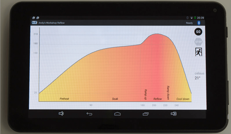
[Andy Brown] is a prolific hacker and ends up building a lot of hardware. About a year back, he built a reflow oven controller. The board he designed used a large number of surface mount parts. This made it seem like a chicken or egg first problem. So he designed a new, easy to build, Android based reflow controller. The new version uses just one, easy to solder surface mount part. By putting in a cheap bluetooth module on the controller, he was able to write an app which could control the oven using any bluetooth enabled Android phone or tablet.
The single PCB is divided into the high voltage, mains powered section separated from the low power control electronics with cutout slots to take care of creepage issues. A BTA312-600B triac is used to switch the oven (load) on and off. The triac is controlled by a MOC3020M optically isolated triac driver, which in turn is driven by a micro controller via a transistor. The beefy 12Amp T0220 package triac is expected to get hot when switching the 1300W load, and [Andy] works through the math to show how he arrived at the heat sink selection. To ensure safety, he uses an isolated, fully encased step down transformer to provide power to the low voltage, control section. One of his requirements was to detect the zero cross over of the mains waveform. Using this signal allows him to turn on the triac for specific angle which can be varied by the micro controller depending on how much current the load requires. The rectified, but unfiltered ac signal is fed to the base of a transistor, which switches every time its base-emitter voltage threshold is reached.
For temperature measurement, [Andy] was using a type-k thermocouple and a Maxim MAX31855 thermocouple to digital converter. This part caused him quite some grief due to a bad production batch, and he found that out via the eevblog forum – eventually sorted out by ordering a replacement. Bluetooth functions are handled by the popular, and cheap, HC-06 module, which allows easy, automatic pairing. He prototyped the code on an ATmega328P, and then transferred it to an ATmega8 after optimising and whittling it down to under 7.5kb using the gcc optimiser. In order to make the board stand-alone, he also added a header for a cheap, Nokia 5110 display and a rotary encoder selector with switch. This allows local control without requiring an Android device.
Gerbers (zip file) for the board are available from his blog, and the ATmega code and Android app from his Github repo. The BoM list on his blog makes it easy to order out all the parts. In the hour long video after the break, [Andy] walks you through solder tip selection, tips for soldering SMD parts, the whole assembly process for the board and a demo. He then wraps it up by connecting the board to his oven, and showing it in action. He still needs to polish his PID tuning and algorithm, so add in your tips in the comments below.


great work.
Sweet
So… you can’t PWN that oven? I’m pretty sure that is how most toaster oven reflow systems work… using a solid state relay .
That particular oven is already pwned.
I see what you did there.
[Andy]’s oven is phase angle controlled, and that is a form of PWM.
Well you could use a bridge rectifier and a IGBT to use PWM over sinusoidal signal. Has some improvements over energy quality but works the same
That android app is a bit of an overkill
so we have complainers for underachieving and complainers for overachieving as well now. Overkill is a completely relative term in this context and he obviously has experience making GUIs so let the man do his thing.
It is. But [Andy] has a point about what he called “landfill Androids”. Massive overkill has become ridiculously cheap. Lots of people already have an Android device, if not more than one. And they can do GUIs easier and better than anything you might build. So might as well reuse, rather than putting a dedicated LCD in a project. Even if you don’t have an Android, they’re cheap enough to justify buying one, especially if you can control multiple projects with it.
A few months back, I realized I can regularly get a nice new Android phone, including prepaid service, for CHEAPER than maintaining service on an existing phone. I think that’s crazy, and encourages the average person to be wasteful. But I’m not the average person, and I can put some extra Androids to good use with a little bit of code. As they are accumulated, they’ll become project GUIs, universal remotes, etc.
Soon as this terms contract is up (might be already, just waiting for the phone a sibling wants to lower in price) I’ll have two very good for their age Android phones laying around. One will be formatted and be just a trip logger for my motorbike; front camera taking a pic a minute or so, GPS logging, g-force logs, maybe audio if state laws get sane, and so on. The other is . . . crap, it was a free phone 5 years ago. And some older Java-based phones laying around because my family is security conscious (or my class mates thought I might be able to salvage the SMD parts for something). Let’s call it 2 usable and 4 “won’t even work for e911 anymore” phones.
Should I scrap them all? Why! The newest will have a good purpose if I can weatherproof it. The old one has some HIPAA stuff and can’t be donated, so why not make the screen into “something” via BT, USB, or serial over audio cable.
Please do not endorse these videos showing the wrong way to solder smds, the mans instructions, iron tips and techniques are wrong, he just done a horrible job on that poor huge pitch ic, he was risking damage both to component and board taking so long to solder each pad, and the end result is of piss poor quality.
Please show this to the viewers https://youtu.be/5uiroWBkdFY it shows a correct and easy way to solder these components.
If you keep showing “how hard” it is to solder smds, the community will never learn and improve their skills, this type of components is here to stay, no amount of whining over the difficulty to solder these will make the industry go back to to pth. These type of pins are a lot easier to solder once you use the correct techniques, show them to the community, there is no need for re-flow ovens apart from bga or lots of components on a board
I would go for a web based interface instead of bluetooth. I used to do that with routers http://www.electrobob.com/web-interfaces/ but I think nowadays it should be possible with the ESP8266 with larger memory. This makes is the most universal way to control the thing, it works on tablet, laptop, phone independent of their operating system.
Cool project, I think that the overshoot is caused by the very small thermal mass of the oven. I have experienced with a regular oven and control can be more precise.