[] decided to build his own thermocouples from bare wire. [Illya] is interested in measuring the temperature of Liquid Nitrogen and for this he needed T-type probes. While you can buy these for about 20 bucks, he felt this was too expensive for what is essentially two pieces of wire and decided to build his own.
Thermocouples use the Seebeck effect, when a piece of metal is hot at one end, and cold at the other the electrons in the hot end will be more energetic and migrate towards the cold end, creating a voltage. While this migration occurs in single metal, it can’t easily be measured (as the voltage will be the same as the measurement point). For that reason thermocouples use two metals in which the migration occurs at different rates. This difference creates an overall migration in one direction, and a voltage can be measured which correlates to the temperature where the metals meet. Thermocouples are extremely common and have many applications.
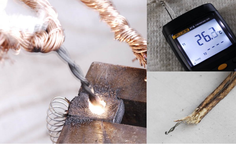
In order to make his thermocouples [Illya] needed to weld the two metals together, and knocked together a quick welding rig using a PC power supply and graphite electrode from a powertool. The graphite electrode is important as it prevents oxidization during the welding process.
The process worked well, and [Illya] was able to make both K and T-type thermocouples and successfully measure temperatures down to -190 degrees C. Awesome work [Illya]!


Depending on the temperature range you want to measure, a solder joint with tin-based solder (the same used for soldering electronic components) is also possible for T-type thermocouple.
If one has a LN2 source why not just evaporate some in an enclosure to create a neutral atmosphere for welding?
I did a quick search and it turns out the materials are pretty hard to come by, especially with glass insulation for more extreme temperatures.
This is a common way of making thermocouples. At work we have a commercial spot welder meant specifically for wire-wire bonding that we use for this purpose. It’s way cheaper than buying them premade. Even better, you can repair broken junctions and reuse damaged probes. Some of our probes end up epoxied in heatsinks so it’s easier to snip the end and reform the junction.
This is definitely a common field repair technique, though a bit rough in the implementation.
I work at a company that makes one of the commercial versions of this tool, and beyond packaging, and a ceramic cavity to hold the welding medium, it’s much the same.
For a production shop though, fixtured TIG welders are more common, but have the added requirement of a shield gas bottle to keep on hand.
Using AtTiny861 with differential gain ( to measure T-probe ) + a cheap spi display you could make a complete instrument for nothing… ( the type K probe ca be found for less than 2$ on ebay )
I had this idea too. The Problem is, the 32x gain ADC from the Attiny861 is not very high, so you want your reference voltage as low as possible. The smallest internal reference voltage is 1.1V, but not accurate at all (+-0.1V). The smallest external reference voltage is 2V, which with 32x gain leads to a voltage range of 62.5mv and therefore a temperature range of over 1300 degrees C with a K-type and bad resolution with the 10-bit ADC.
Also keep in mind you will need another temperature sensor for cold-junction compensation, or at least a PN-junction (diode). The accuracy of the internal temperature sensor of the AVR is very poor and probably not good enough.
The simplest you could do to get a decent accuracy is use an external temperature sensor chip for CJC and an external reference voltage chip that you can compare / calibrate your internal reference to.
The cheapest is probably a diode with your internal gain amp as CJC and a calibration table for your internal reference stored in EEPROM.
Both solutions will have a temperature range of about 800 degrees C and therefore a resolution (not accuracy!) of about 1 degree C. Accuracy? Let’s not talk about that..
Stupid question for power-supply aficionados: Will one 12V line from an ATX supply the entire unit’s current? Could you use just one of the 12V connections from an ATX or would you have to use all of them?
This has to be the most annoying question ever, about ATX power supplies. The answer is no, especially since part of the “entire unit’s” current is supplied on other voltage outputs such as the 5v line. There is a very nice label on 99.9% of ATX power supplies that says how much current can be supplied by each voltage output. Some even specify combinations of current on the 12 and 5 volt or 3.3 volt lines.
The other part of the question is what is meant by “line”. There is a bundle of yellow wires that carry the 12v “line” or output. They all solder into the power supply’s PCB at a heavy, generally solder-reinforced trace. If the question is really “can just one of those yellow wires supply the unit’s entire 12v specified current”, then there are several answers. One answer comes in the form of another question, “why not just use all the yellow wires?”. A more scientific answer would be “yes, but only if one wire is sufficient size to carry that much current”. But then it even misses the point, and the question is moot when you take a peek at the PCB and realize that the output lines are grouped by color and the 12v and 5v wires all solder to their respective traces.
In spite of your annoyance, you gave a very clear and thorough answer… it’s too early to decide who won the internet today, but you’ll surely at least be a finalist.
For me ‘very clear’ and ‘rambling’ are two different things.
Whoa there, cowboy.
You’re not wrong, but [Thinkerer] isn’t asking a stupid question either. Label or no, it’s not immediately obvious.
Many supplies (especially the >300W ones) have separate 12V supply rails inside. AFAIK this is done to keep transients localized and to keep costs down. These rails are typically distinguished by having yellow wires with a stripe (or lack of) for each separate rail. These are organized by connector, so the main ATX and 4 or 6 pin ATX12 cables that normally go to the motherboard should all have the same stripe pattern, while the PCIe 12V and drive power connectors may each have different 12V patterns.
So yes, wires of the same color on a PC PSU are all functionally identical. To get the full rated power for each one, you need to gang them together since just one wire alone is going to melt. And when a supply has more than one 12V supply, make sure to only gang together wires with the same stripe pattern.
If you’re starting a project and need 12V at high current, consider hacking an old server supply. Some older HP Proliant hot swap supplies are 12V only at 200-400W and have a nice card-edge connector that can be directly soldered to. These run $10-15 on eBay and are built better than many PC supplies.
Thank you, I did not know about the separate “rails” in the 12VDC supply of the PC power supplies.
Hmm… For a project like this I would probably use a cheap old plain PC supply.. because I already have several that aren’t doing anything but take up space. Don’t we all have old computer junk laying around these days? The nice thing about this project is that you really only need a strong surge current. It isn’t going to take long to make your spot weld.
I’m working on building a reprap and your advice of power supplies sounds like a good idea for that. I was going to use one of my nicer old PC supplies for it. Then again.. I also thought that later, after everything is working I might upgrade to a 25V supply. If I am going to order anything I don’t already have I may as well order the thing I plan to use in the end.
Those server supplies are popular for RepRap because they’re more stable at higher currents than PC supplies which may be noisy unless most of the rails are loaded.
If you’re going for higher voltage and aren’t going to use a heated bed, consider a 19.5V laptop supply. You’ll have to find a hotend heater that works at that voltage (hint: a 50W 24V heater cartridge is 33W at 19.5V) but a used Dell D-series 90W brick should have enough grunt for 4-5 steppers and a 33W heater.
I guess this is what I was seeking clarification on – thanks to everyone.
seconded for server power supplies. bought a hstns-pa01 power supply for $19 shipped on ebay. 12 volts 74 amps on 120vac, 12 volt 106 amps when run off a 220v line.
the best thing is when you actually draw that much current through parallel wires, you get to see them jump when the current starts flowing.
I used 0.8mm mechanical pencil lead and my bench supply to weld a type K junction. I actually had to dial down the voltage to below 10V as it keeps melting the wires. :) It was only drawing a couple of amps.
It’s nice to know, but for the $20, seems like a lot of hassle to set up unless you need several. Along the author’s line of thinking, I’m surprised the author didn’t dismantle a dead motor instead of buying a brand new brush.
I’m actually a little surprised he didn’t just solder them; you don’t exactly have issues with melting solder if you’re measuring LN2, and the resulting two junctions in the tip are at essentially the same temperature as each other, so the magnitude of the Seebeck effect in the solder pretty much just cancels out. That’s what they had us do in the basic engineering experimentation course at my college, anyways, with no measured ill effects.
We make T type thermocouples by twisting and soldering all the time.
Really? And they have the same / similar response and limits?
yes. there is no reason to solder or spot weld a joint unless you are doing very specific (laboratory things with a tc amplifier, your own calibration, etc) you can create a perfect Type T thermocouple by twisting only, i challenge anyone to show me that a pile of twisted junctions will alter the measurement in any significant way. Once you are a pro you can even twist, clip, and squeeze to create an extremely small (single) junction, but it is needless unless you are doing weird PhD fluid mechanics things, eg work with fast response AWG30 thermocouples where the perfect sphere junction has some particular advantages.
What about at low temps? Won’t contraction cause gaps in the junction if it’s not bonded somehow?
Think about the physics of it: a thermocouple basically is operating off the sum of the Seebeck voltages down the chain. Even if the solder were to have a nonuniform temperature, if both sides of the solder joint are at the same temperature, the total voltage through the solder will be zero – for the same reason you have to use dissimilar metals to get a thermocouple at all. In a little solder joint, there’s very little material and distance to cover, so it’s pretty much all at a constant temperature unless you’re doing something quite extreme.
In fact, old-school thermocouple use had three sections – both leads to the measurement device were the same metal, one went to a temperature reference (say, something at the triple point of water), and the other went to the object to be measured. The leg between the reference and the object to be measured is made of the other metal. That way, the voltage you measure across the thermocouple is /only/ the leg from the reference to the target, the rest cancels out, and you look up the voltage you’re getting out in a table for the reference. (The Seebeck effect is nonlinear, so you do have a bit of math to do or have pre-done to get to a temperature, and you do need to know what the starting temperature is. Modern thermocouple measurement devices measure the temperature at the device and essentially simulate the reference juncture.)
Measuring the temperature of liquid nitrogen? That’s like needing to measure the temperature of boiling water (it’s always the same). 77 K….
always the same when it is boiling, yes… as long as the pressure is the same.
Interesting, but not really a novel idea. When I worked in the industrial maintenance sector, it was common practice for us to weld together our own thermocouples, usually type K. We simply twisted together the ends of the thermocouple wire and hit it with a MAPP torch until it was properly welded together. It worked every time.
That being said, this is a welding technique I haven’t seen before, so kudos to [Illya].
You don’t even need to weld the wire. Just twist them together and it works. It is not as durable and the measurement is taken along the length of the twist instead of a point, but in a pinch, it’ll work just fine.
And then take the twisted joint and smack it with a ball peen hammer to increase the contact area.
Twist and smack them on a vise, works fine, last long time.
30 comments on a thermocouple? Must be too hot to play outside.
We want thermocouples to measure how bloody hot this heat wave is!
Just give it a sligh twist and strike it with a hammer. I usually take my dick for that!
You give your dick a slight twist and strike it with a hammer? Damn…
Bet you wish there was an edit button now.
Woah, I got hackaday effect :) Thanks, folks. Idea of making own thermocouples was due to fact that majority of cheap thermocouples from usual go-to stores or ones bundled with cheap thermometers are not accurate for temperatures below -50°C. And for extreme overclocking it’s important to know if your CPU is at -100°C or -110°C, so accuracy and linearity is important. Welding also helps for reliable results with daily abuses of thermocouple thermal cycling.