[Brek] needed to store 64 bits of data from his GPS to serve as a last-known-position function. This memory must be non-volatile, sticking around when the GPS and power are off. Solutions like using a backup battery or employing a $0.25 EEPROM chip were obviously too pedestrian. [Brek] wanted to store his 64 bits in style and that means hand-wired core memory.
OK, we’re pretty sure that the solution came first, and then [Brek] found a fitting problem that could be solved, but you gotta give him props for a project well executed and well documented.
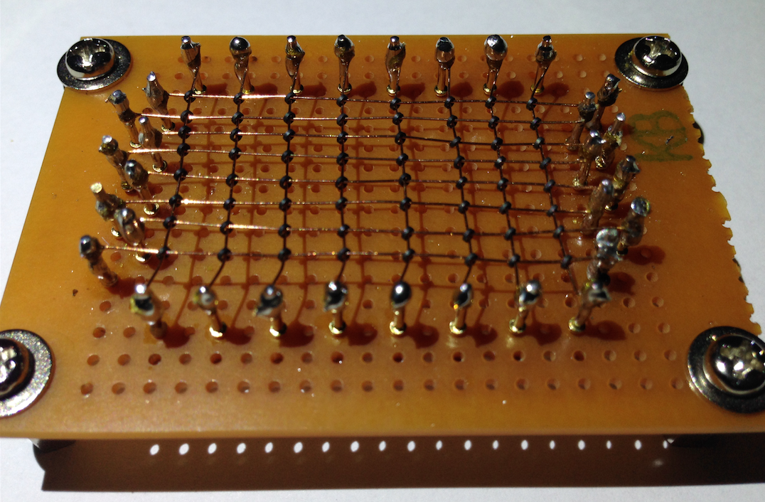
Core memory is basically just a bunch of magnetizable rings on wires. When you pass enough current through a ring it becomes magnetically charged (North or South) depending on the direction of the current. Once magnetized, if you try to re-magnetize the core in the same direction, nothing changes. But if you flip the polarity of the ring, it emits a short electric pulse in the process. Sensing this pulse (and re-writing the bit back to its original state if necessary) buys you one-bit-per-ring of memory that remembers even when the power goes off.
 You could string the cores up independently, but that’s a lot of wiring. The trick to making core memory (halfway) reasonable is the fact that a current that’s not quite strong enough to flip the polarity of a ring doesn’t do anything.
Look at the way the cores are wired up in a matrix. If you want to select a single core, you can apply half the current to one of the y-axis wires, for instance, and then another half current to a single x-axis wire. Now the one ring to get enough current to flip state is the core in the cross-hairs; all the other rings in the x or y direction only get half.
What’s amazing to us young(er) whipper-snappers is that this was the dominant form of computer memory from the 1950s to the beginning of the transistor age in the mid-1970s. (Come to think of it, my father’s PDP-8 had core memory cards that I vaguely remember seeing as a kid. The sheer wiring required for 4KB was ridiculous.)
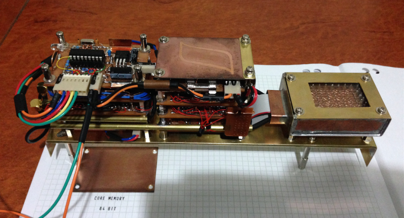
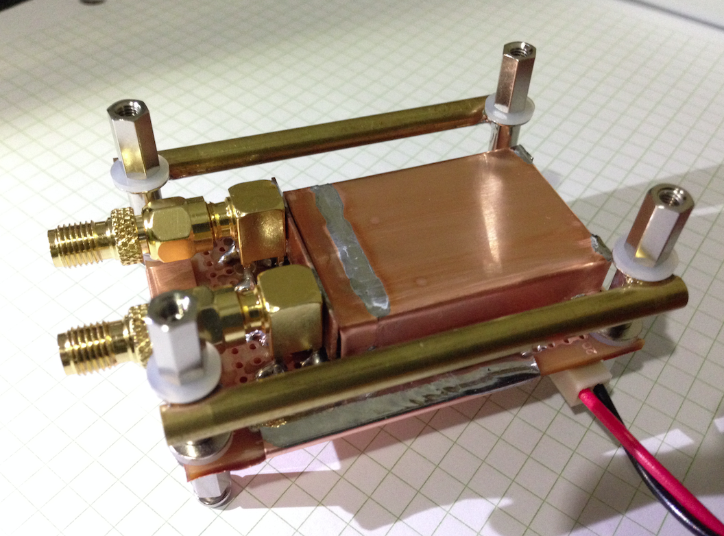 Now back to [Brek]’s project. He’s added some shift registers and H-bridge drivers to handle the logic and current requirements respectively. The sense amplifier lives in a tidy copper cage. The whole build is a sweet testament to over-the-top, bespoke retro engineering. And he gets extra points for the hysteresis logo on the top cover. Go check out his project.
Thanks, [Brek] for all the work and documentation!


I love the use of brass and copper in projects. It looks really good, and reminds of the beautiful handmade equipment from the early 1900’s.
Now that’s hipster computing
That’s MacGyver computing. Hipsters wouldn’t be able to do such a thing by themselves.
Not hardly, bro. He didn’t even use an arduino. Electrons shall not flow unless through arduino.
MacGyver doesn’t need an Arduino. :p
MacGyver’s Arduino was a roll of duct tape.
I have some old core memory sitting around somewhere including the support circuitry at the end of the chassis. The cores are considerably smaller than the ones used in this project and the wires are about the thickness of human hair. This is a neat project – thanks for sharing.
With core memory that data should be safe against ionising radiation. Is this the guidance system for a homebuilt Project-Pluto?
Well yes, the core memory is, but the support circuitry is not.
Depends, doesn’t look like those chips are anything too complex. Admittedly all I know is they’re DIP-14 or whatever, but it doesn’t take a lot of logic to drive core. It’s the more complex, fine-featured chips that suffer from radiation upsets. Simple SSI logic might be OK. That’s if this thing were going to go into space, which it isn’t, so it doesn’t matter, but anyway…
The original core-based machines used discrete transistors, with later ones using early logic chips, DTL and the like. So you could fly an IBM mainframe in space, if you could get it off the ground.
The complexity of the IC has nothing to do with flight certification. But radiation testing could be done, and flight certified rad-hard devices are available from most IC manufacturers.
I know certification is a specific process. But the finer the details on an IC, the tinier the transistors, the more susceptible a transistor is to being flipped by a cosmic ray. A larger feature, or “component” on an IC is less likely to be upset.
Of course that’s not enough to rely on, so they use sapphire bases and things. But it’s still true.
No, it’s not true. The smaller the transistor the less active volume there is to interact, thereby reducing the likelihood of an ionizing event causing a charge change in the the junction.
@Dave – incorrect. it’s a question of geometric redundancy in each gate. the target size is still comparable – it can hit *anywhere* on the silicon and cause a problem. but if you have a gate that’s 200nm across (lets say square, planar, 20nm thick), and a cosmic ray strikes it and knocks a 10nm spherical disruption in it, you’ve still got quite a bit of the original geometric size left for durability
by contrast, if you ahve a 50x50x10 nm gate structure and you get that same 10nm spherical disruption, you’ve got a hole that’s easily going through the entire thickness of the gate, and possibly severing a supply trace
No, it’s a question of density and interaction volume determining the probability of ionizing radiation interacting with the semiconductor.
@Hyratel – You are thinking of charged particles (like cosmic rays), but I was thinking of non-massive ionizing radiation, like gamma and X-rays.
In your case, you are correct. The higher the density of gates, the more likely the damage.
Re “The smaller the transistor the less active volume there is to interact,” that doesn’t account for all the other transistors surrounding it. ANY of which will suffer just as much. As you say yourself, “the higher the density of gates”, where smaller transistors just about always means more dense gates.
That only applies to charged particles.
i think the space shuttle challenger used core memory, they were actually able to recover it and do a core dump, in the literal sense of the term.
I read the first Shuttles actually used Apple IIs. 5 of them, in a voting configuration. The reason for 5 being, if any of them disagreed with the vote, it could be turned off, and you’d still have 3 left to give a majority in further voting. Of course 4 wouldn’t do, because it allows for ties.
Challenger was finished in 1983, far too late for anyone to use core, unless they had a really perverse reason for it.
They used, for a time, GRiD laptops / tablets on board some of the shuttle missions, they used bubble memory. That was non-volatile, was going to be the next big thing in the 1980s.
The Shuttles never used Apple IIs! They where a space qualified IBM system based on the 360/370 family main frame! The first shuttle flew in 1981! Nasa would never have used a COTS system for a fight system in 1980 and they would not have touched an Apple II with a 10 foot pole for a mission critical system.
You’re right, it used AP-101s according to the Internet. Damn you, whoever wrote that book I read 30 years ago!
Apparently 4 of them ran in sync (which is wierd cos it allows for a tie), with a fifth programmed in a different language, just in case. The language of the first four was HAL/S, where “S” stands for “Shuttle”. Apparently named after some guy named Hal, but we know better!
According to Wikipedia, https://en.wikipedia.org/wiki/Magnetic-core_memory, the Apollo Guidance Computer, used core memory. Maybe that’s what you were thinking of.
Support interface is 100% Texas Instruments, supposed to be a homage because they made silicon sense receiver chips and drivers for core. Core shift register logic is the best documented on old military (YouTube) videos.
I think the same interface could be done with core logic.
Apparently back in the early days, core memory was made by teams of women, trained to KNIT it out of wire!
I dunno enough about knitting to suggest a pattern. Perhaps it was too tricky and delicate for machines to do.
I wonder how hard it would be to device a way to simply glue a drop of suitable metallic powder around the junction point to act as the core?
http://worldpowersystems.com/archives/Ivall/Magnetic-core-arrangement.jpg
I don’t see why they could’t be mass-manufactured with a mold which has places for all the wires and holes in place of the cores, to which some sort of powder-and-glue mixture would be squeezed and solidified.
That might work.
Or, suppose you manufacture a thin printed circuit board with the required wiring on three layers. At each crossing you’d have two holes, and again you use a mold to press powdered magnetic core material into rings that go through these holes, thousands of rings at a time.
Like two large vias next to each other that get filled with the material, and then two bridges of the material on top and bottom to complete the magnetic “ring”? One or more traces can pass in between the two vias.
Precisely.
The way these ring cores are manufactured is by pressing and then firing them in a kiln to sinter the powder. The result of gluing the powder instead is that it introduces a distributed “air gap”, which means the core needs more current to switch, but other than that it should be a perfectly workable solution.
I wonder what alloys and metals you can use to make a magnetic core, where it could be sintered after it’s been placed on the wire grid? Without destroying the wire, obviously. Some sort of glue that evaporates or whatever, during the sintering process. A bit like firing clay, but magnetic.
Then you’d be able to weave the grid fairly simply, and just press the cores on like you were making cookies in a factory. Would remove all that annoying threading.
I would whatever technology that they use to make SMT ferrite bead filters would be useful for this. They just have to make it more a squarish block with the extra connections.
http://www.murata.com/~/media/webrenewal/products/emiconfun/emc/2011/06/14/en-20110614-p1/en-20110614-p1_img0002.ashx?la=en&h=338&w=500
To what avail, though?
Alternate history – imagine what could have come out of having extremely cheap core memory back in the day.
Some really bloated programs, probably. Nobody would ever have learned how to squeeze code into impossible gaps, and create baroque ways of coding just to save 2 bytes.
Interesting idea. To what avail? To the best of my knowledge (and there was considerable research),
the machines eventually developed to weave the matrix could never do the sense wire.
I don’t know if it would ever be considered again for military, but it does have some quality,
slower than our RAM, but faster than our EEPROM, and non volatile like our EEPROM.
But why core RAM could meet some requirement today, I wouldn’t know.
Thanks for the comments (and the write up) :)
But does the wire have to be round in order for it to work? I imagine probably not and maybe different wire shapes could even lower the amount of current required to set and read bits.
The wire cross section shape doesn’t affect how much current you need. You need a certain amount to create a magnetic field of certain magnitude to cause the core to magnetize.
The only thing that reduces the current is if you manage to loop the same wire twice through each core, in which case the current is halved.
A machine to automatically thread core memory was invented, just in time for silicon RAM chips to make core memory obsolete.
Find the movie “The Dish”. It’s about the large radio antenna in Australia (still in active use) that was used during the Apollo missions for tracking when no antennas in the northern hemisphere could see the spacecraft. The movie is based on actual events. There was a power outage, which would not have been a problem except for a peculiarity in the design of the tracking computer. An unavoidable part of the power up process was a destructive refresh of the core memory.
So when they turned the computer back on, the tracking program was wiped, and had to be reloaded from magnetic tape, which took several hours. But there was worse! They had no idea where the Apollo 11 ship was or had been due to the memory wipe, so they could not command the dish to move to the right location to communicate with the ship. Eventually they figured out with good old pencil and paper and brainpower where to point the dish and once a signal was picked up it was able to seek to the strongest signal and operated perfectly for the rest of the mission.
Another story, not made into a movie, about that dish is for over 20 years it was picking up random noise. They finally tracked down the source this year, the break room microwave oven. Every time someone zapped their lunch the big antenna would pick it up. Apparently not quite as on the ball as the guys there in the late 1960’s. ;)
This is fantastic! I love it when the old and the new can meet in a new way like this!
making core memory is the only reasonable solution to all your NV memory needs!
Punch cards will survive more hostile conditions. Especially if made of metal.
well i consider punch cards to be more like ROM than NVM
Well sure, but you could create a re-writable punch card.
You could? Out of card? That can be punched? In a normal card-punching teletype? Or even not in one. How would you do that?
well it wont be a punch card but maybe some sort of dry erase situation?
im not sure
core is still best XP
sliding metal gates on a metal sheet…wonderful idea!
Re-writable punch cards… think hanging chads.. en mass. https://en.wikipedia.org/wiki/Chad_%28paper%29 not sure they would be particularly durable… maybe you could manage a few dozen re-writes before they became unhinged.
I was imagining a device, where a bit could be activated electrically or magnetically, and then read optically, or by direct electrical contact. Each bit would be bi-stable, like in those electrophoretic (bi-stable cholesteric) displays, or those “flip-dot” displays. Or perhaps using two small surface mount inductors, mounted on opposite sides of a circuit board, with a small through hole directly beneath them both. A small droplet of ferro-fluid in that passageway allows one to attract the ferro-fluid to one or the other inductor with a pulse of current. (ideally) the droplet would stay there due to surface tension. Then the position of the droplet is measuring using the change in inductance.
How about a bump-card, with pieces of shape memory metal held in a thin frame? To erase a card, flatten it between a pair of rollers. To write, apply spot heat to the pieces of SM metal you want to be 1’s. They return to their original bump shape. If SM metal was cheap the entire card could be made of it with a default shape of all 1 bumps.
Or if you insist on the default state being zeros, have the system call a bump a zero and heat the whole card to erase.
This is very cool, and brings back memories. In 1979, I got to work with a computer control system for editing with time-coded video tape that used a PDP11. It had, IIRC, 48K of core memory, that held not only the programme, loaded from paper tape, but also the Edit Decision List which recorded all the edits. The core memory was very stable and the great thing about the system was that you could switch it off at the end of a session, and when you switched it on the next day it was exactly as you left it. If the programme crashed you could use the front panel switches to restart in such a way that the EDL memory wasn’t over-written.
Later versions replaced the core memory with CMOS which was terrible. You had to save everything to 8″ floppy, and the memory was very susceptible to static. We had to have special conductive carpet in the equipment room otherwise just walking past the computer rack would crash it.
when I started programming in ’68 we had a variant of core memory called plated wire core memory which allowed much denser stacking of the cores..
its was in the univac 9000-9200 I learned BAL,cobol and rpg on
advantage was unlike regular core memory it could be machine assembled instead of having lines of workers stringing core memory planes by hand
other variants were vacuum deposition thin film memory (also could be machine fabricated)
think the RCA-501 I also programmed on was regular core
the IBM 360-195 I also worked with used the thin film core memory variant..
not sure of the CDC 6600 or the cyber n170 used on the PLATO IV network employed
an old timer,
boy does this bring back memories :)
Those look like really small toroids seems like their unobtainium these days. My dreams of buying toroids like to make a transormer and knitting my own core memory’s a pipe dream… Back to plotting how to make an acouhstic delay line is more realistic … and a mumble tub memory’s more temporaly in sync with relays as the logic family to make a cpu. So fooey on your core after all… but it sure’dbe cool…..
Actually you can buy those cores from Ebay.
https://www.ebay.de/itm/5000-Miniature-RAW-FERRITE-Magnetic-CORES-5221-3-3114-53-FOR-CORE-MEMORY-BOARD/302520781100?ssPageName=STRK%3AMEBIDX%3AIT&_trksid=p2057872.m2749.l2648
Hello, I wanted to see what is the url to the project itself. The link https://hackaday.io/project/6824-core-memory-64-bit is dead. Thnk you
Same. Sorry to see the project’s no longer online.
what a great page. Ive been searching online for how to create core memory. for some reason loads of the results are about making children happy, apparently that creates core memory?