Historically when hams built low power (QRP) transmitters, they’d use a crystal to set the frequency. Years ago, it was common to find crystals in all sorts of radios, including scanners and handheld transceivers. Crystals are very stable and precise and it is relatively easy to make a high quality oscillator with a crystal and a few parts.
The big problem is you can’t change the frequency much without changing crystals. Making a high quality variable frequency oscillator (VFO) out of traditional components is quite a challenge. However, today you have many alternatives ranging from digital synthesis to all-in-one IC solutions that can generate stable signals in a wide range of frequencies.
[N2HTT] likes to build radio projects and he decided to take an Si5351 clock generator and turn it into a three frequency VFO for his projects. The Si5351 uses a crystal, so it is very stable. However, you can digitally convert that crystal frequency into multiple frequencies over a range of about 8kHz to 160MHz.
The chip has two PLLs that multiply the crystal frequency by a programmable amount. Then you can set each channel to start with the crystal frequency or either PLL and divide it by an integer or a fractional amount. As you might expect, the integer divisions result in a more stable output, but if you really need a particular frequency and can accept some jitter, you can get almost anything you want out of the device.
The device [N2HTT] used is in a tiny 10 pin MSOP package, but there are plenty of inexpensive breakout boards available. You control all the multiplying and dividing by sending configuration data to the chip via I2C. There’s even a software package that can tell you the best settings for the frequencies you want to generate.
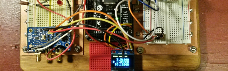
One thing of interest is the breadboard the VFO is built on. [N2HTT] used an Arduino and a small display along with an encoder to control the chip. But the chip generates some high frequencies and common wisdom is that solderless breadboards aren’t good for high frequency. Acting on a tip he read in a magazine article [N2HTT] took a bamboo cutting board and then affixed standard solderless breadboards to unetched copper PCB material. He then made sure the PCB ground planes were well connected and grounded. It seems to work (you can see it working in the video below).
The output of the chip is a square wave, so if you wanted to use it for radio applications, you’d probably have to low pass filter the output to get a sine wave. The device is only as accurate as the crystal and will exhibit some phase noise and jitter (especially if you don’t have integer divisions). However, having a wide range programmable frequency source for a few bucks is a great building block for lots of different projects.
In fact, we covered a project to use the same part to implement a digital communications mode a few months ago. There’s also more than one Arduino library out there. Since it is I2C, you can use it with many other processors, too.


OK, yeah the breadboard groundplane trick is good info. Thanks!
Does anybody who test this can tell more about it, please?
How does it work compared to a breadboard without a ground plane?
not to be confused with the Si535 chip whic is crystl only and single output.
Datasheets here: https://www.silabs.com/products/timing/clock-generator/si535x/pages/si535x.aspx
Si5351 = crummy phase noise. There are poor Si5351 PN test results from people who don’t know what they’re doing floating around that claim otherwise. Don’t believe them. The Si570/571 parts are a better choice, especially for receivers above 10MHz. At 7MHz (40m) and below over relatively sort signal paths (not weak signal work), you can get away with even a terrible receiver. And for that kind of work, the Si5351 is just fine.
Actually this design was intended as a VFO for a low power CW transmitter on three bands – phase noise not an issue. Final project will include low pass filters selected by relay by the Arduino, since the si5351 puts out a square wave.