One of the hardest things you’ll ever do is mesh your electronic design with a mechanical design. Getting holes for switches in the right place is a pain, and if you do it enough, you’ll realize the beauty of panel mount jacks. This is especially true when using Eagle to design a PCB, but with a few tricks, it’s possible to build 3D printable pieces directly from Eagle designs.
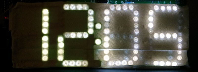
[Tyler] built a clock with a bunch of LEDs. While the clock worked great, there was a lot of light leakage around the segments of his custom seven-segment numbers. The solution is a light mask, and [Tyler] figured out how to make one in Eagle.
The first step is to draw a new layer on the Eagle board that defines the light mask. This is exported as an EPS file in the CAM processor that gives him a 2D drawing. At least it’s to scale.
The next step is to install Inkscape and install paths2openscad. This turns the two-dimensional drawing into a 2D object that can be rendered in OpenSCAD and exported as a 3D printable STL file.
Does the project work? The results are great – the entire light mask is a single-wall print, and since this light mask doesn’t need any mechanical strength, it should hold up well. The clock looks much better than before, and [Tyler] has a new technique for making 3D objects for his 2D PCBs.


Intriguing. I wonder how easily this technique could be applied to other PCB layout software.
At work, we have the luxury of using altium. We just export the PCB 3D model as step for mechanical designers to fit in their 3D drawings. Any free PCB packets that have 3D support?
KiCad has a 3d export function; I’ve used to render boards in blender. Don’t know how it does with importing into cad packages, but I’m sure it’s doable.
There is a package for KiCAD called StepUp that exports into STEP format:
https://forum.kicad.info/t/kicad-stepup-new-exporter-for-3d-mcad-feedbacks-are-welcome/1048
http://sourceforge.net/projects/kicadstepup/
Diptrace has the functionality built in, even in the free version. If you have 3D models of all of your components, you can export the board assembly from Diptrace and open it right up in Solidworks ( or any 3D cad)
Another way is to save an intermediary IDF/IDX/ASC file from your ECAD software and turn it 3D with Solidworks’ plugin ‘circuitworks’. It’s included even if you don’t install Solidworks Electrical. Circuitworks has the advantage that features on the board will be separate, coloured and correctly laid out in Solidworks’ proceedural design system. That means it’s far easier to include in an assembly.
I love his comments at the bottom of the blog – my experience with those CAD packages has been similar, sadly I was not able to express my feelings in such a graceful and un-swear-word-infused manner.
Sometimes I wonder if developers from commercial packages work as contributors to FreeCAD just to cripple it.
Have they yet made the common sense, logical addition of scroll bars to the view window? WTH should I have to change to a special mode simply to pan the view around?
Afaik, eagle can export brd files directly to dxf.
It’s even easyer than the described process,
eagle save dxf, open in sketchup, edit 3D and export as stl
You got it. That’s how I laser cut solder stencils out of Kapton from my EAGLE files. Export the cream layers to dxf and I’m cutting in minutes.
Yup, this is how I’ve been getting my screw holes lined up between the boards and my mech parts. FreeCAD opens my dxfs without problems and i can lay the piece ‘over’ a sketch. Getting it to use the dxf as reference geometry is a little tricky (much easier in Solidworks, but alas I don’t have the money for a license nor am i willing to install a virus), but it gets the job done for 3d printed parts :D
EagleUp is a free tool to get a 3D visualization of your PCB (components are on you) for EAgle files in Sketchup. I use it all the time for making enclosures and whatnot.