There are cheap LCDs available from China, and when plugged into an Arduino, these displays serve as useful interfaces or even shinier baubles for your latest project. [Michael] picked up a few of these displays in the hope of putting a few animated .GIFs on them. This is an impossible task with an ATMega microcontroller – the Arduino does not have the RAM or the processing power to play full-screen animations. It is possible to display 3D vector graphics, with an updated graphics library [Michael] wrote.
The display in question uses the ILI9341 LCD driver, found in the Adafruit library, and an optimized 3D graphics driver. Both of these drivers have noticeable flicker when the animation updates, caused by the delay between erasing a previous frame and when a new frame is drawn.
With 16-bit color and a resolution of 320×240 pixels, there simply isn’t enough memory or the processing power on an ATMega microcontroller to render anything in the time it takes to display a single frame. There isn’t enough memory to render off-screen, either. To solve this problem, [Michael] built his render library to only render pixels that are different from the previous frame.
Rendering in 3D presents its own problems, with convex surfaces that can overlap themselves. To fix this, [Michael]’s library renders objects from front to back – if the pixel doesn’t change, it doesn’t need to be rendered. This automatically handles occlusions.
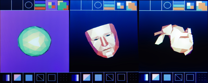
In a demo application, [Michael]’s LCD and Arduino can display the Stanford bunny, a low-poly 3D face, and geometric object. It’s not a video game yet, but [Michael] thinks he can port the classic game Spectre to this platform and have it run at a decent frame rate.
Video of the demo below.


Like old schooll demos on Attari/ZX Spectrum/ etc Assembly and other Demo parties.
Hey yaaaa Back to the Past
Time to upgrade ATmel MCU SRAM with another model of MCU ;)
That is some pretty amazing stuff.
+1
+1 and amazing job. Thanks for contributing the source back. very very cool.
A 20MHz AtMega has roughly the computational power (though not the addressability) of an 8MHz 68000. FIGnition, which is based on an AtMega supports a proper bitmapped frame buffer via serial RAM (which it copies to PAL or NTSC composite video in realtime). Watch it generate a Lorenz Attractor a few times faster than a Mac Plus can!
https://youtu.be/e5P0lX6VT1M
OK, so it’s black and white and a fairly low-res (it only uses 3Kb of it’s 8Kb serial RAM), but just to illustrate that serial RAM can support frame buffers at a decent rate: so, a 32Kb serial RAM could support video as good as an Atari-ST.
Having an SD card makes it easier. Behold Jonnection’s “Take on Me” demo playing on an Arduino Nano driving a Nokia 5110 LCD at 84×48 1-bit monochrome with PWM audio: https://www.youtube.com/watch?v=Sq3vodSSfbg
Do you think there’s enough juice in the ATMega to display a simple vector map off an SD card? Say we use a 176×144 display and only draw most basic stuff (roads, large polygons like water/forest, icons and labels) derived from OSM data. That could make us the cheapest GPS. I wonder whether HOTOSM could make use of these in humanitarian operations.
Alternatively, is there much that could be gained by going to the cheaper end of the Cortex M0 series? Think LPC111x or STM32F1x – these are already as cheap as AVR.
If you store the maps on an SD card I imagine it will work. There’s no need to update maps rapidly, so a visible redraw step is fine. I agree that using the Cortex chips is probably a better idea, I’m not sure the Atmega328 offers any advantage except providing a tougher optimization puzzle.
The coolest thing is that’s writen in C++. Now imagine going ASM, I bet you could squeeze even a little bit of performance.
From my inspection, avr-g++ is generating fairly efficient assembly, but there is room for improvement. The “flood” routine should maybe be re-done as a jump table in assembly rather than the loop-unrolling thing that’s there now? I suspect most of the bottleneck is in actually sending/receiving pixel data, so minimizing the instructions related to that would be the priority.
A little additional context missing from the summary. In addition to CPU and RAM limitations, the ILI9341 is usually connected via SPI, which is often the biggest bottleneck. According to the datasheet, it only supports up to 10Mhz or so. Though I’ve been able to drive one up to 40Mhz, others didn’t have similar success. A person more knowledgeable than me suggested there seem to be multiple manufacturers of the chip, including some unlicensed clones, which may account for the different real-world performance.
I’ve done a good bit of coding for the ILI9341, and I’m quite impressed by this demo!
Though I’m not clear on something. If I understand correctly, [Michael]’s storing some extra info in the unused bits of the pixels of the ILI9341 frame buffer, and has to read them back to determine which pixels need to be updated. But over SPI, reading is just as expensive as writing. Reading every pixel to determine if it needs to be repainted, then writing the only the necessary pixels, would actually take more SPI time than just repainting every pixel! So I don’t understand how [Michael]’s approach could be an effective optimization.
Also, the ILI9341 works by first setting a square area to operate on (which can be a line or a single pixel), then you can contiguously write/read that area by transferring only the pixel data. Changing to another area requires quite a few additional non-pixel bytes to be transferred. So sometimes transferring a few pixels don’t need to be transferred, is actually more efficient than skipping those pixels. At one point I was trying to optimize text drawing on a blank background, and thought that if I skip the unneeded background pixels, it would surely be faster. I was surprised to find that on average, it was not.
It’s a tricky problem. If you either always write or always skip unneeded pixels, then you’re always wasting some amount of time; but which approach is better is highly dependent on what you’re drawing, and neither approach is always optimal. If you always select the optimal approach on a pixel-by-pixel basis, the time used to perform that optimization can exceed the time you save; even if only CPU time is used for this, but *especially* if supplemental SPI reads are needed.
What I do to when I need to avoid flicker, is to render a complete display line at a time – both background and foreground. This fits easily in the MCU’s RAM. Then the entire line is written out contiguously via SPI, during which time the MCU can work on rendering the next line. The ugly flicker resulting from clearing the entire background then drawing the foreground is avoided, as the image just repaints from top to bottom. Any pixel overlaps occur in the line buffer, even without explicit occlusion checking; so there are no expensive overlapping SPI writes at any time. My method doesn’t know if pixels are unchanged from the previous frame, and therefore don’t need to be repainted, but it doesn’t need to do any SPI reads. (Unless it’s doing alpha blends with the previous frame, which it can do, for some funky effects.)
If I were to use my display library for something like [Michael]’s demo, I’d also keep track of the first and last pixel in each line of the 3D display area that had a non-background color for the previous frame. That would easily eliminate two contiguous regions when drawing a line, a simple but effective optimization.
It would be interesting to see which would be faster, my approach or [Michael]’s. Like I discovered with the above example regarding text, sometimes you get a surprise. A couple of optimizations in my library made it into the library for the Arduino Due after some comparative benchmarking. Unfortunately there’s no chance of such a comparison here, I’ve never done any 3D coding!
“The ILI9341 provides the 8/9/16/18 bit parallel system interface and 3/4 line serial system interface for serial data input.” The shield is hooked up with the 8-bit parallel interface, which is where some of the speed comes from. It would be nicer if all 8 data lines were on the same port. The optimizations were more about avoiding the subjective appearance of redrawing the graphics in-place, so they are slower than just sending pixel data, but do not flicker. I’m not sure how to render vector graphics one scanline at a time, with only the display memory and the limited memory on the Uno, but I’m sure there are ways. I think this would probably require a pretty sophisticated algorithm? Storing the first and last location of image data on each line would be a nice optimization that I’d considered but didn’t implement as I was about running out of program and stack space. If you submit a pull request with this optimization I’ll merge it in.
Oh! I didn’t realize you were using the parallel interface. That’s a great advantage.
Here’s an outline of how I draw vectors, one scanline at a time:
1) Swap the coordinates if needed, so that the lowest Y is always the vector origin.
2) Place each vector in a structure instance, with any possible precomputed values (typically Bresenham).
3) Create a linked list of pointers to the structure instances, sorted by ascending Y origin. This is the “inactive” list.
4) Check the first vector in the “inactive” list. If it starts on the current scanline, remove it from the “inactive” list, link it to an “active” list instead, and repeat #4.
5) Draw each vector in the “active” list. But only until the current Y of a vector leaves the current scanline. Or until the X reaches the endpoint, in which case delete the vector from the “active” list.
6) Until the last scanline is reached or both lists are empty, increment scanline and goto #4.
If you’ve ever examined or written a filled polygon draw routine (with unlimited vectors, rather than a simpler filled triangle), you’ll recognize this as a subset of the logic.
I’d sincerely like to help out with the first/last used pixel per line optimization, but I doubt I can, as I work on PIC rather than Arduino. My submissions to the Due library were possible to successfully port “blind”, without being able to test on the target hardware. Don’t think that will be the case here.
Hey thanks for the pseudocode! I’ll think about it. I’m supposed to be writing my thesis and not procrastinating with microcontrollers, but we’ll see.
Just had an idea, knowing nothing about the chipset you’re using… nor whether this is in any way relevant to your project…
If the parallel interface of the chipset can handle the speeds, one way to squeeze *really fast* loading of huge amounts of consecutive identical pixels might be to put the “Write” strobe on the PWM output of an AVR with a PLL. The PLL in my Tiny861 is supposed to saturate at 85MHz, but as I recall, I’ve pulled ~128… that’d be capable of strobing a pin at 64MHz. Getting the timing right to get an exact number of strobes… well, that’s the “fun” part ;)
In my line-by-line screen-update routine, I use a “row-segment-buffer” which is essentially an array of [Color, Length]… if it weren’t for the fact my screen requires a steady pixel-clock, the row-seg-buf would lend itself *really well* to this idea.
Am impressed with what you’ve accomplished! Did I read right that it’s C++?!
You just blew my mind. It would require a different shield pinout to get a PWM enabled pin on the clock line, but that’s just some soldering. I’m not sure how to tightly control the number of PWM pulses sent, will examine the datasheet. Good idea!
That is a cool idea! If the pixel write area is still predefined on the parallel interface, this could work even if the timing is loose and too many strobes are sent. No problem if it wraps back around to the beginning of the area, since all pixels are identical.
Good point! Although setting a rectangular region will take a few tens of clock cycles more than what the current implementation does, which is just move the upper left corner of the bounding box. After reviewing the datasheet, I’m not sure PWM can offer any speedup on the Atmega. The Atmega executes one instruction per cycle. In fast strobe mode, it is simply alternating loading one or two registers onto PORTC, which should in theory just take two clock cycles, if I understand correctly. This would seem to be just as fast as the fastest PWM mode possible? But! there is perhaps the possibility of turning on PWM in the background and returning from the function call early. This would mean that subsequent drawing commands will need to check if a PWM flood is still active and stop it. I’m not sure whether this would really gain you much, between the extra instructions needed to start and stop PWM, and the extra instructions related to setting and re-setting the full bounding box as opposed to just the top-left, it might be something of a wash.
Respect.
I’m just writing this to let the author know that this project inspired me to try to build my own 3D project for Arduino! Keep it up! Mine is not as good, but for me it’s good enough! https://github.com/fabio914/arduinogl