The ability to inexpensively but accurately measure distance between an autonomous vehicle or robot and nearby objects is a challenging problem for hackers. Knowing the distance is key to obstacle avoidance. Running into something with a small robot may be a trivial problem but could be deadly with a big one like an autonomous vehicle.
My interest in distance measurement for obstacle avoidance stems from my entry in the 2013 NASA Sample Return Robot (SRR) Competition. I used a web camera for vision processing and attempted various visual techniques for making measurements, without a lot of success. At the competition, two entrants used scanning lidars which piqued my interest in them.
A lidar is a laser range measurement device. The name is a combination of the terms LIght and raDAR and not, as commonly suggested, an acronym derived in a manner similar to its forerunner, “RAdio Detection And Ranging”. The term was first used in 1963 according to Merriam-Webster. Some of the early use of lidar was measuring clouds and the surface of the moon by Apollo 13. As lasers were reduced in size, other uses were found, including as a rangefinder for military purposes.


A single laser beam can only provide the range to a single object. Just as aircraft control radar swings a beam through the sky, a scanning lidar sweeps the laser. The application of lidar for autonomous mobile devices requires scanning of a wide area both vertically and horizontally to provide a point cloud of distance measurements. Something similar might be done with an infra-red sensor, as we’ve seen previously but the accuracy is not as good as with a laser.
Distance measurement can be done in multiple ways but there are two principal ones used. One measures the time of flight of a laser pulse while the other uses the angle of deflection of the laser beam.
Time of Flight Measurement
You’re familiar with how basic radar and sonar works – send out a pulse and measure the time it takes to receive the return signal. The time divided by the speed of light or sound gives you the distance the signal traveled out and back. Divide that by two to get the distance to the object. That’s time of flight (ToF) measurement.
As you might suspect things get tricky given the speed of light. A pioneer in computers, Rear Admiral Grace “Amazing Grace” Hopper would hand out 11.80” pieces of wire to demonstrate the distance light travels in a nanosecond in vacuum. With robots that is the magnitude of the distance we’re interested in measuring. It’s difficult to measure less than a meter sending out just a pulse and timing the return signal because the signal returns in about 7 nanoseconds.
One technique around this is to continuously modulate the signal by amplitude or frequency. The phase difference between the transmitted and received signals is proportional to the distance to the object. A lidar using modulation can measure down to centimeters.
There are a number of commercial providers of ToF based scanning lidars but the price is a bit higher than the most hobbyist’s would spend. A relatively new entrant, PulsedLight, offered a single beam ToF lidar within the price range of hackers but their suppliers are all back ordered.


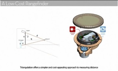
Triangulation
The triangulation lidar uses the same technique as the Sharp infra-red distance measuring sensors which hackers have been using for years. The transmitter is a single source but the receiver is a 1 or 2 dimensional array of receivers. The offset of the receiver elements from the transmitter creates the baseline of a triangle. The outgoing and return signal are the other two sides of the triangle. Simple trigonometry provides the distance from the baseline to the object.
The Optical Society describes these and other techniques used for measuring distance.
Neato Robotics Vacuum Lidar
What I didn’t know when competing in the 2013 NASA SRR is that Neato Robotics released a vacuum cleaner in 2010 using a scanning lidar to sense the vacuum’s surroundings. This allows the robot to avoid obstacles instead of bumping into them as previous robot vacuum’s were doing.
 Sparkfun did a tear down of the vacuum and investigated the lidar. A long discussion starting in November of 2010 ensued on the Trossen Robotic forum as hackers dissected the vacuum with much attention to the lidar. There were even small prizes offered for hacking the lidar.
Unfortunately a number of the links in that thread no longer exist but it is still worth reading since many details are laid out in the messages. Some other threads on the forum have additional information. One especially interesting find is a research paper that preceded the Neato lidar but served as the basis for the final design. It outlined the details necessary for Neato to create an engineered product.
The good news is a wiki exists with a summary of information about the vacuum and the lidar. One of the active hacking participants, [Nicolas “Xevel” Saugnier] created a small USB interface board to power the lidar and connect to its serial interface. In the summer of 2014 I obtained a couple of the lidar units and the boards as I looked toward entering the 2015 NASA SRR. I got the lidar units working using [Xevel’s] Python software and packages available in the Robot Operating System.
The scanning lidar allowed Neato Robotics to implement Simultaneous Localization and Mapping (SLAM) using the distance measurement data. This allows the robot to plan the cleaning path rather than using the previous bump and random movements, a Drunkard’s Walk, of earlier vacuums. This allows the Neato to completely cover a room more quickly. Note in this video of a Neato demonstration how the robot builds a map of where it’s been and the obstacles it encounters. Especially note how it uses the lidar data to neatly circle the one obstacle.
Pi 2 and Lidar
I’m still very interested in robots although I’ve given up on the SRR contest. The lidars have been sitting on the shelf luring me like mythical Sirens. I finally succumbed to their call when I realized the lidar serial interface was a perfect match to a Raspberry Pi’s since both work at 3V3 levels. This would eliminate the USB interface. A similar effort is [Thomas Jesperson’s] in 2014 who used an STM32F429 board and produced a video of the lidar in action.
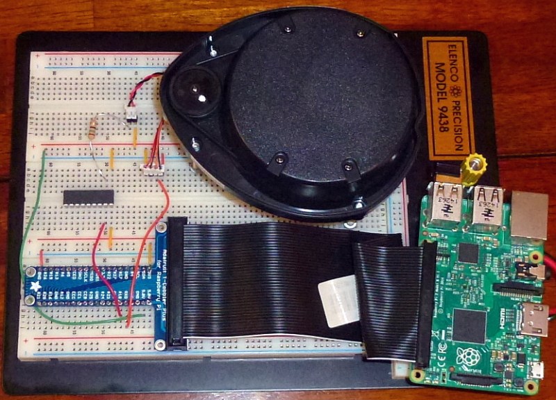
Lidar Physical
The lidar is a sealed unit with a motor hanging from one end. The motor drives a turret that rotates at around 300 rpm. The turret contains the laser and receive sensor and by spinning provides a 360 degree scan of the surrounding area. The laser and receive sensor have two optical ports out of the turret. There are two short cables with JST connectors coming from the lidar. A two pin connector provides power to the motor. A four pin connector provides 5V power to the control circuits and the 3V3 serial interface. The pinouts are:
Red: 3V3 or PWM
Black: Ground
Black: Ground
Red: 5V
Brown: RX
Orange: TX
In the vacuum, the motor is powered by a 12V source using PWM at around a 25% duty cycle. This means the motor needs around 3V to run at the right speed and subsequent testing by the hackers showed this is true. The USB interface board runs the lidar from the 5V input from the USB connector using PWM controlled by a a PID (Proportional Integral Differential) loop to maintain the motor’s speed. Why use PWM and PID? To maintain a constant RPM for the spinning turret as it wears and collects dirt, dust, and other detritus. In my testing I noted that the motor will turn the turret in either direction depending on the positive and negative connection. The interface still works fine but the sequence of the data points is going to be reversed. Normally the turret turns counter-clockwise.
A word of caution: in some early units the interface used 3V3 so connecting them to 5V may destroy the interface.
My original hook-up between the Pi and the lidar was quick and dirty. I connected the motor to the Pi’s 3V3 output and it worked. The output from the Pi 3V3 is limited to 50 mA by the specifications and the lidar Wiki says the motor would draw 64 mA. I measured mine and it drew considerably more. I also connected the interface’s TX pin to the Pi’s RX (pin 10). Using CuteCom under Raspbian Jessie I could read the data when the turret was manually spun. With those basic tests out of the way it was time to get a little more serious.
I elected to use a ULN2803A Darlington Transistor Array I found in my parts cabinet to drive the motor. This IC easily handles the current needed to drive the motor and includes the protective diodes required for driving an inductive load. I didn’t intended to do PWM of the motor but did want to turn it off and on. I connected the Pi’s 5V on pin 2 to the red wire on the motor connector. The black wired connected to the ULN2803A through a 15 ohm resistor to drop the voltage. This setup low-side configuration for controlling the motor. The interface cable is connected to the 5V, ground, and RX pins on the Pi.


To test the motor control I used the mapping of the GPIO pins to the file system directory /sys/class/gpio. Each GPIO can be controlled here once the pin is exported. Commands can then set pins the direction and turn the pin on and off. The commands I used controlled GPIO 18 (pin 12):
echo 18 > /sys/class/gpio/export
echo out > /sys/class/gpio/gpio18/direction
echo 0 > /sys/class/gpio/gpio18/value
echo 1 > /sys/class/gpio/gpio18/value
The ‘0’ and ‘1’ when echoed turn the pin off and on, respectively. This worked and I could see the data using CuteCom.
One interesting result occurs if you are connected to the serial port and then apply power to the interface. The lidar generates a welcome message:
Piccolo Laser Distance Scanner
Copyright (c) 2009-2011 Neato Robotics, Inc.
All Rights Reserved
Loader\0x09V2.5.15295
CPU\0x09F2802x/c001
Serial\0x09KSH34313AA-0140854
LastCal\0x09[5371726C]
Runtime\0x09V2.6.15295
Also, if you manually spin the turret, a message saying “Spin” appears and advises there is a command capability available by sending a break or three esc characters. Information on the commands is available on the Wiki.
Lidar Software
Now to create some rough software to see how all this works. Of course I used C++ so I installed the tool chain for the Pi 2 and find that the compilation speed is sufficient for development. I started using the Geany programming editor and makefiles; a setup I learned about while working with the Python code for the lidar. It handles multiple programming languages and I’ve adopted it as a general purpose text editor on Ubuntu and Raspian. But I eventually abandoned Geany and installed Eclipse CDT on the Pi when it wouldn’t properly reformat the C++ code after editing. Eclipse works surprisingly well on the Pi. I was actually a little disappointed in the switch since with Geany I was re-learning how to work with makefiles, a skill I’ve lost working with Eclipse.
While looking for information on programming the GPIO with C++ I found the WiringPi library by [Gordon Henderson]. It not only supports raw GPIO programming but supports many Pi daughter boards. An additional appeal to me is it has a serial port interface so I didn’t have to get into the details of that on Linux, which would have been new to me. Eventually, I even used its simple thread capability to handle an absurdly minimal user interface. [Gordon] also has a utility you should check out for controlling pins from the command line more completely than writing to the directories as I showed above.
The final piece I found in WiringPi is the ability to do hardware PWM on the one GPIO pin capable of it on the Pi. That is GPIO 18. I’d originally used GPIO 4 (pin 7) to control the motor but switched when I found this capability. The code currently sets a constant value for the PWM but eventually I want to add (and write an article about) a PID (Proportional Integral Differential) control system loop to maintain constant speed. Setting up WiringPi, a thread and the the PWM on GPIO 18 is easy:
	wiringPiSetup();
	piHiPri(10);  // set program priority to run better
	piThreadCreate(key_read);

	pinMode(turret, PWM_OUTPUT);
	pwmWrite(turret, 950);
The thread is there simply to stop the program when any key is entered and return hit. When run is set to false, the main thread reading the serial input quits and the program exits after turning off the turret. The actual thread is dirt simple:
PI_THREAD(key_read) {
	cin.get();
	run = false;
	return 0;
}
Reading the serial input is simple, just reading characters, but the data itself, while straightforward, requires a little bit banging. There are 360 samples per revolution of the turret so the amount of data at 5 revolutions per second is massive. There are 90 packets each containing four data points. Each point is represented by four bytes of data: distance, signal strength, invalid distance bit, and invalid strength bit. In addition, each packet begins with a start byte, an index byte which is the packet number, and two bytes for the turret rotation speed. The packet ends with two checksum bytes. Here’s how I mapped that data into structures:
	struct DataPoint {
		bool invalid_data;
		bool bad_strength;
		float distance;
		unsigned int strength;
	};

	struct Block {
		unsigned int index;
		unsigned int speed;
	};
I didn’t get into storing the data packets, just reporting them to verify I was seeing good data and my calculations looked good. The distance data is an integer reported in millimeters which I converted to inches. The code for the checksum is on the Wiki but I haven’t implemented it yet.
Wrap Up
This is just the start of working with the Neato lidar but a good one. The hardware works well and the basics of the software are in hand. I can get the data and see that it is valid. The WiringPi library is a good find for continuing in my efforts with the Pi.
Next steps are to get the checksum routine working, expand the so-called user interface to allow controlling operation of the turret and adding a PID loop to maintain a constant speed of rotation. Since the UNL2803A chip is there I’ll use it to control the power to the interface. I also want to look at cross-compiling the code from my desktop and doing remote debugging. As I make those changes I’ll organize the code into classes and see how I can use it on a robot.


Did a similar project a while ago. The lidar is great fun for its price
http://youtu.be/KnspWPlBM_o
Can you share where you can source a lidar?
Got mine from eBay. Search for neato lds.
So Neato for $150 or lidar lite for $100..
http://www.robotshop.com/en/pulsedlight.html
I built an architectural plotting rover that mapped out floor plans for a college project a couple years ago using the lidar lite. It was very easy to use (I2C) and relatively cheap. I’d recommend the lidar lite simply for ease of use but I don’t have any experience with the Neato.
The Neato rotates taking a measurement every degree, the lidar lite doesn’t. You have to figure out how to make it rotate and what angle its pointing in.
Actually I had to tear it of a used vacuum, but it was like 3 years ago, not long after initial discovery of this neat device by diy scene. Getting used neato was only choise back then
Hey Ruddy, I did salvage a Lidar from Neato Botvac. When I try communicating it with cutecom, all it shows is lots of break tag and few more like oxe0, 0xff, 0xc0. Did you face something similar or can you help me with the insights on these errors?
Is the pinout for the unl2803a correct? The datasheet for the unl2803a says that the out pin for in_7 is pin 12 (not 10), that gnd pin is 9 (not 8), and com is pin 10 (not 9).
is the pinout for the unl2803A correct? The datasheet says that the out pin for in_7 is pin 12 (not 10), gnd is pin 9 (not 8), and com is pin 10 (not 9).
Sonnds like a worthwhile project. I’m guessing good for remote locations, off the grid.
How can you say that LIDAR is a combination of LIght and raDAR if there is no radar used? Radar requires RAdio but you are using just a laser so it seems that LIDAR really is an acronym for LIght Detection And Ranging.
Because ‘RADAR’ is RAdio Detection And Ranging. The DAR part has NOTHING to do with radio.
Replace the RAdio part with LIght and you make LIDAR from RADAR.
Well, radio signals are actually invisible light signals. Radio waves travel also with the speed of light.
It is a combination of the WORDS Light and Radar. Not the technologies in light and radar. The point is to say that it uses light to do the same (or similar) thing as radar does.
That’s like saying “How can you say that Deflategate is a combination of ‘Deflating footballs’ and ‘Watergate’ if it didn’t even happen at the Watergate hotel?”
RADAR isn’t a word, it’s an acronym. kjoehass is correct.
Oh, come on. Take the 5 letters of RADAR. Remove the “RA” (which come from the word “radio”) and replace with “LI” (which come from the word “light”). Now you have LIDAR. This is the origin of these 5 letters together, which we pronounce lie-dar, used to describe time-of-flight range measurements using light, usually laser.
In fact, up until about 10 years ago, it was common to see the terms lidar, ladar (LA from laser), and “laser radar”, all to refer to this technology. Lidar won out in popularity.
The reason for the analogy to radar is because lidar works on the same physical principle but using a different wavelength of the EM spectrum (light waves vs radio waves). So it wasn’t just the combination of terms to make the new word, but the borrowing of technology principles. It’s a combination of both terms and technologies. What’s fundamentally different is the part of the spectrum.
kjoehass made the mistake of thinking that the “combination of light and radar” requires the use of radio waves, that it couldn’t be a linguistic combination or a technological combination that replaced radio with light. kjoehass was mistaken.
For the record, although radar started as an acronym, commonly used acronyms are considered words themselves, including scuba, laser, and radar.
Now that we’ve had the pedantic discussion about the origin of the word lidar (and nobody cares whether we call it a word or not), how does any of this thread add anything useful to anybody?
I commented because the original text was confusing, and you have confirmed my belief. I didn’t make a “mistake of thinking”, the author made a mistake of writing. The text should have said “the word LIDAR is a combination” rather than just “LIDAR is a combination”.
It just struck me: if you mounted the LIDAR turret horizontally, and rotated that mount on a vertical axis, would that not give you a 360(ish) 3D scanner?
Robots like big dog of boston dynamics just do that to achieve a kind of 60*360 scanner. The second motor needs to spin faster. A full 3d scanned could be made also using a line laser and camera, but cameras usually are slower than simple phototransistors.
I’ve seen a video where a lidar that might have been a Neato was mounted on a pan/tilt. When the robot moved the path ahead was scanned by the lidar sweeping the area. It was mounted such that the scan to the rear was blocked. It might still be usable for SLAM but I’m not sure. It’s something I’m thinking of trying.
The scan I saw from a Hoyuku (sp?) was of a 6 or so separate lines covering floor to about 6 feet. I’m not sure how they do this.
Here’s my PI bot which in the most recent update uses lidar… I’ve also tried some other techniques along the way
https://hackaday.io/project/394-autonomous-pi-bot
I’d like to make a Pi Bot that’s just a couple of brushed motors and AA batteries duct taped to a Raspberry Pi Zero. That, I think, would be the most comical representation of our current state of technological excess.
anyone happen to know what class laser this uses?
For liability reasons it is Class I (aka “eye safe”)…although the caveat is that there is a safety interlock which turns off the laser when the turret is not spinning.
Hello, guys. Could someone tell me how to verify the data sent by LIDAR? Show me the data as an angle and position. Thank you very much in advance.
Hi, I’m also been researching about this –
Have you figured it out? :)
Why are those things so HUGE, and EXPENSIVE??
Samsung and Apple “phones” used to have LIDAR modules, and they can be bought for *two*-figure sums!
But what interface do they use? Who even made them?
Because I’m not paying $23,000 or something for a massive car unit, when there’s ones for $23! Especially when I want to build something that is supposed to go on your toes (or shoes if you love in the *wrong* climate ;)!
s/love/live/ !! ;)