Last time I introduced you to two relatively inexpensive and somewhat portable scopes: the EM125, which is a cross between a digital voltmeter and an oscilloscope, and the Wave Rambler, which is a scope probe with a USB connector attached. Both of the devices cost about $100, and both have their plusses and minuses.
This time, though, I wanted actually to look at some real-world signals. To make that easy, I grabbed yet another scope-like thing I had handy: an Embedded Artists Labtool. This is an interesting board in its own right. It is an LPC-Link programmer attached to an LPC ARM board that has several high-speed A/D channels. However, I’m not using any of that capability for now. The board also has a cheap ARM processor (an LPC812) on it that serves only to generate test signals. The idea is you can use the Labtool in a classroom with no additional equipment.
The Labtool’s demo CPU generates a lot of different signals, but with only one channel on the test scopes, it didn’t make sense to look at, for example, I2C data. So I stuck with two different test signals: a varying pulse width modulation signals and a serial UART transmitter.
Baseline Signals
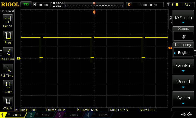 To get an idea of what the signals ought to look like, I measured them both with my current favorite bench scope, a Rigol DS1104Z. As you’d expect, it was easy to capture the signals on this scope. Here’s the PWM.
In this case, the PWM was at nearly 99% (you can read that out at the bottom of the screen). The LPC812 cycles this output from 0 to 100% fairly quickly and I happened to catch it at that point. The UART is slightly more challenging since it sends a burst of data with a long gap in between. By using normal triggering (instead of auto) the display nice and stable: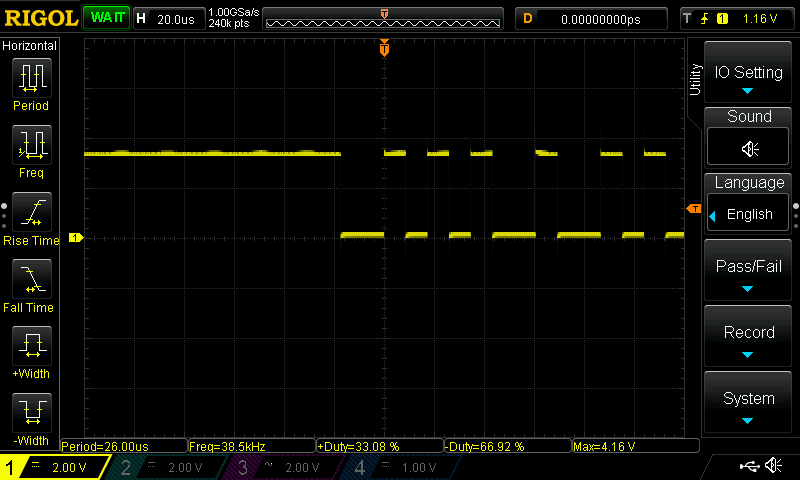
Naturally, a single event trigger would work too. The Rigol, of course, could also decode that UART string, a feature none of the other scopes here could match. Of course it isn’t a $100 scope, either. For reference, the 50 MHz version is about $400. Then again, it has four channels, so its cost per channel isn’t really more than the two scopes we are looking at.
Using the Wave Rambler
The Wave Rambler uses some Windows software and my main desktop doesn’t run Windows at all. However, I do have a very cheap Windows tablet that is serviceable and has a full-sized USB port. When I first ran the software on the tablet, I was confused that the screenshots in the documentation didn’t look right at all. It turns out the tablet’s default setting is to have 125% zoom on the screen. This caused the Owon software to incorrectly compute the location some user interface elements and they were drawn off the screen. The solution was to reset the zoom level in the Windows control panel.
Connecting the scope probe to the circuit wasn’t hard. There’s a spring hook like you’d find on a normal scope probe, although there is no skirt for your fingers to grab when pulling it down. Between that and the size of the probe itself, using that is fairly awkward. You can remove the spring hook if you just want to probe, again, just like a regular scope probe.
The device comes with two grounding methods. There is a clip lead for general use and a little spring that lets you ground to a test point ground. This is useful at high frequencies to avoid inductance in the ground wire. However, at the 25 MHz rating of the instrument, you probably won’t be looking at anything that needs that.
The software looks like it belongs to a larger scope. You can see there are provisions for multiple channels, for example, even though the Wave Rambler only has one channel. There are features you probably won’t use, like pass/fail matching. However, this is a real strength to the Wave Rambler. Need an FFT? The software does that. Want to export the data? Easy to do.
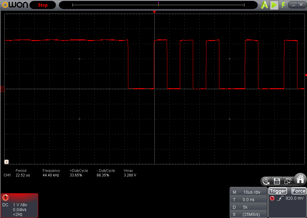
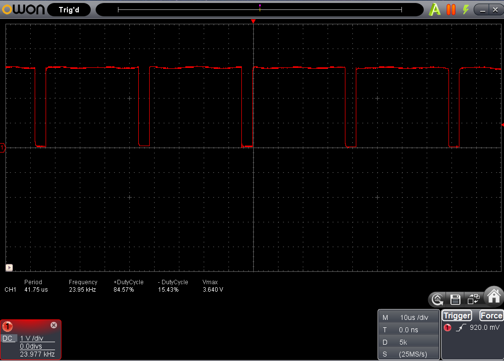 The software’s interface is a little unorthodox, but it works fine. You can select several trigger modes (edge, pulse width, and slope). You can add measurements to the display just like the Rigol does. Here’s the PWM capture, for example.
You can see the measurements at the bottom of the trace. The home icon is where most of the menu selections reside, although pressing some on-screen elements will do obvious things like change from AC to DC coupling. The large A at the top of the screen is the auto settings, which can be handy with a small scope like this.
 You can use the software to set what parameters the little track ball controls. Honestly, I didn’t find the trackball very useful so after a few tries I ignored it and just used the software settings. Your mileage, of course, may vary.
Since the software provides a variety of trigger modes, it was easy to capture the UART data, although the software won’t offer to decode it for you:
Overall, the results were pretty good, if you can get used to the awkwardness of using a big fat scope probe. I wish the software ran on other platforms or, at least, there was Sigrok support for the device (which would also take care of the data decoding).
Using the EM125
The EM125 is certainly handy. With the kickstand, a charged battery, and a normal scope probe, there were not a lot of strange wires or awkward connections. It also didn’t need a laptop or a tablet. Depending on what you want to do, that could be a good thing or a bad thing.
It is good for portability. You can throw the EM125 in your tool kit and you don’t need much else. It comes with a nice case and I put a USB charging cable in it along with a small set of tools. The downside is you can’t do all the fancy things the Wave Rambler does in software, so you’ll find no FFTs, no captured images or data, and nothing beyond basic triggering.
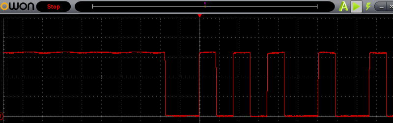
Here’s an actual photograph of the EM125 reading the PWM output from the board:
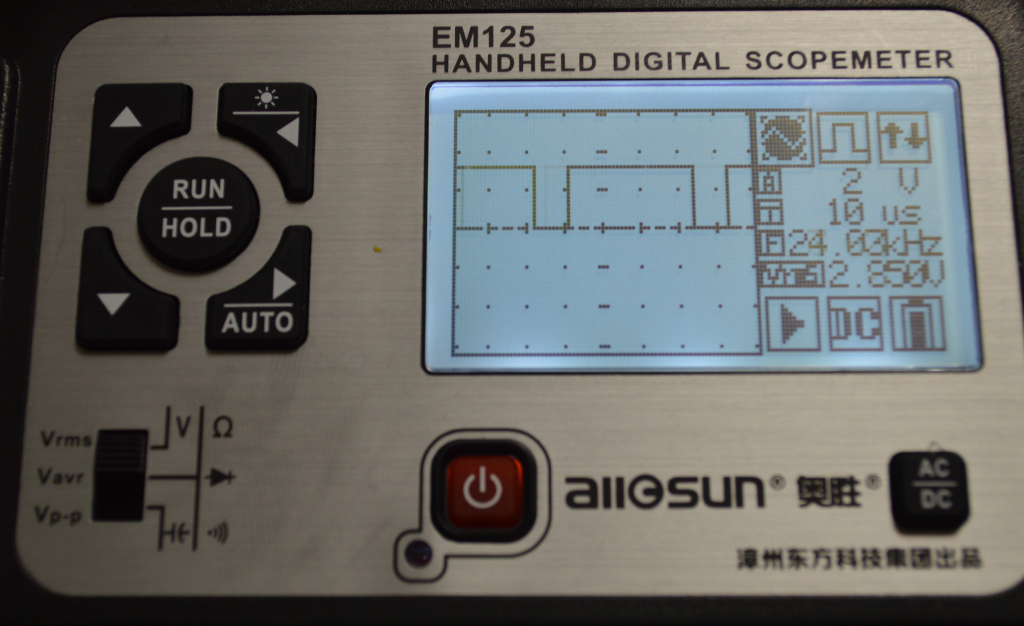 You can see the backlight is nice. The display, though, is a bit confusing. On the top right there are three icons. These icons, along with the two text items below them, are the menu system. You use the arrow keys to go left and right to select an icon. Then the up and down buttons make changes. The first icon sets if the device is a scope or a meter. The second sets the trigger mode. The current mode is essentially an auto mode which is suitable for this capture. The third icon lets you set the trigger level.
If the menu cursor goes down to the numeric fields, you can set the volts per division (currently 2V) and the time base (currently 10 us). The other text and icons are informational (the frequency, the voltage, the current run/stop mode, the input coupling, and the battery charge).
Pressing the left key and holding it will toggle the back light. Pressing the right key and holding it will cause the scope to do an auto set when you release the key. So operation is simple, but then again, the results are simple as well.
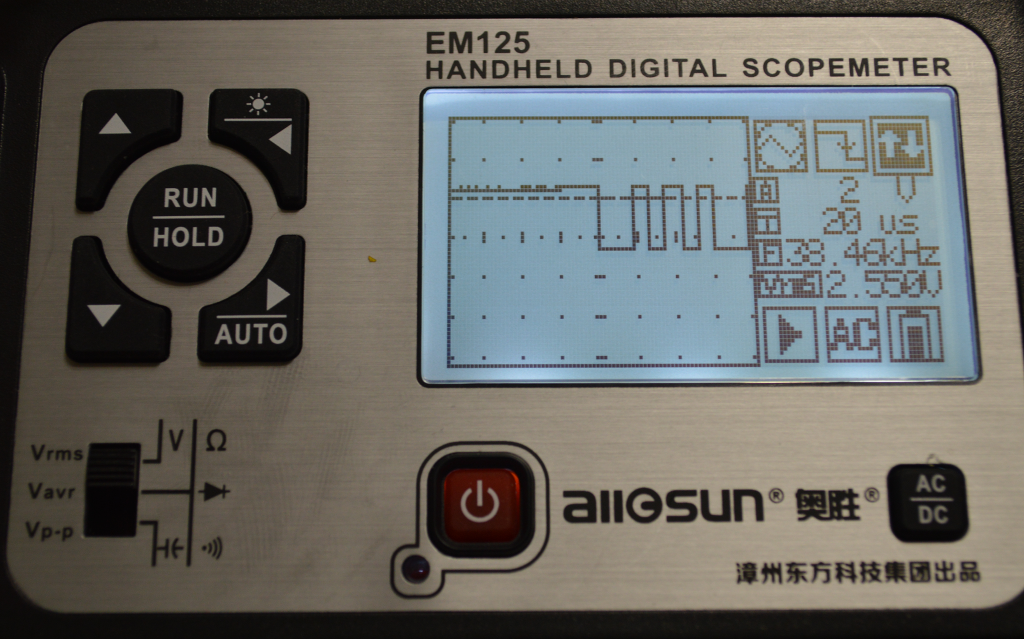 I was afraid the UART output would present a small problem since the scope doesn’t offer a choice between auto and normal trigger modes directly. However, it appears that when the trigger mode icon looks like a plain square wave, it is in auto mode. If you select a rising or falling edge, the scope enters normal mode. That means that until a trigger occurs, the instrument will hold the last image. That makes the UART output easy to capture.
Notice the arrow on the falling edge of the square wave in the trigger mode icon? That’s normal triggering on the falling edge. There is no single trigger mode, although if you are quick enough you can press the hold button, though that can be frustrating.
Conclusion
As I mentioned in the first installment, if you are buying one scope, you ought to try to buy something better than this. You can easily get a nice new scope for a few hundred dollars and used scopes can be found that don’t cost any more than either of these two. However, these little scopes do have their place. The Wave Rambler gives you almost as good performance as a traditional scope, as long as you have a PC nearby, only need one channel, and are reasonably dexterous. The EM125, on the other hand, has edged out my normal volt meter in my travel tool kit. Having a scope–even a limited one–is so much better than just having a junk meter, that it is worth the investment.
Of course, if you really want portability, maybe you’d be interested in a watch. If $100 or even $400 is too cheap for your blue blood, maybe you’d like a 62 GHz scope, instead. If you decide on that one, you might want to cash in a Powerball ticket first. That scope runs about a half million dollars!


I have a Hitachi 20MHz dual-trace scope that I bought back at the dawn of recorded time, but a couple of years back I sprang for one of these: http://www.seeedstudio.com/depot/DSO-Nano-v2-p-681.html. I wasn’t expecting a whole lot… but it’s been surprisingly useful for sub 200 kHz work, and especially with microcontrollers, serial interfaces etc.
I got the v3 a year ago or so. It is a lovely little thing
I’ve also read the old article where the 15$ ‘scopes’ were dismissed, but I recently (1 month ago) bought a DSO138 – ‘some assembly required’ – and it’s the most portable scope I’ve had for less than the price of an original arduino.
I stuck a 9V battery clip to it since it won’t run with only 5V: it needs to generate the negative rail.
For most real-world scenarios you don’t really needs a 1Ghz scope, a few years (decades) ago they weren’t even around.
In my case I need to see the waveform coming from my motorcycle’s speed sensor since I suspect the magnets driving the Hall sensors have degraded which makes the speedometer cut out. I also need to stick a current clamp to see the current draw while cranking to see whether the wires are falling apart or the starter is shorted.
I have an e-bike which boasts CAN support and can take a fancier ‘dashboard’. This means they must be sending somehow CAN signals on one of the 4 wires.
For the above cases a 2Msps scope will do and with a printed/lasercut case and a 9V battery you’re set.