So you’ve just taken apart a hard drive, and you’re looking at all the pieces on your desktop. You’re somehow compelled to use them all in different projects. Why not pull out that very high quality bearing that keeps the platters spinning at high RPMs and build this simple anemometer with it? That’s what [Sergei Bezrukov] did, and it looks like a perfect el cheapo project.
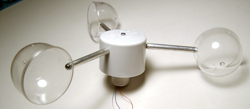
The build is fairly low-tech and entirely sufficient. The cups are made from plastic containers that used to contain pantyhose. A Hall-effect sensor and a magnet take care of measuring the rotations, feeding its signal into a PIC that calculates the wind speed from the revolution rate. The rest of the housing is PVC, with some other miscellaneous parts found at the hardware store.
To calibrate the device, [Sergei] made a second hand-held unit that he could (presumably) drive around in a car to get a baseline wind speed, and then note down the revolution rate. Once you’ve got a good reference, holding the portable unit up to the permanent one transfers the calibration.
But the star of the show, that lets the anemometer spin effortlessly, is the sweet bearing that used to spin a hard-drive platter. If you haven’t played with one of these bearings before, you absolutely should. We just ran a post on taking apart a hard drive for its spare-parts goodness so you have no excuse. If you’re feeling goofy, you can mount one onto a board, step on it with the ball of your foot, and spin. They’re quality bearings, and you’ll be surprised how quickly you can spin as you pull your arms in.
Thank [Matt] for the tip!


Why use a hall effect sensor when you have the brushless motor from the hard drive?
I was wondering the same thing. Treat it like a generator and add a schmitt trigger so you can count nice clean pulses.
The windings put an extra load on the anemometer and will limit the minimum wind speed sensed.
You only need one winding “in circuit”, so what extra load magnitude are we talking about, is it going to drop the minimum speed that much. I mean are we talking about things down at a level that are below what is filtered out as potentially erroneous anyway?
Take a brushless motor with an iron core and spin it, you will find with just one winding and see how it “cogs” even without a load on the winding. It’s not the winding, it is the stator, and it has to go. Otherwise the cogging will kill your low wind speed sensitivity. There are a lot of people that have been making anemometers out of hard drive motors for years and they all do it the same way, use a hall effect to sense the magnets in the motor.
I was hoping for some science, like has anyone actually measured it or is it all assumptions based on tradition? Are these people even properly calibrating their constructions so that it can be quantified? I wouldn’t ask except that I am genuinely interested in DIY weather stations and wish to know as much as possible rather than just copy other people’s work without learning. Ah never mind I have a dead drive here, I’ll work it out myself, like if at such low RPM the forces are relevant….
I can’t feel any cogging in any of the hard drive motors I’ve handled. Still, the stator is not necessary, as you say put a hall effect sensor in there triggered by the magnets already in the motor. No sense adding external magnets that may unbalance it.
Some probably use ironless stators. I have not taken a hard drive apart in a very long time.
Generally speaking, harddisk motors are designed to be cog-less….
Dan, any results/progress yet?
please post your results when you do figure it out :)
I would if people were more helpful, should I use a schmitt trigger because that means the signal can be very low with little resistance across the coil? Is there any trick to how the coils can be connected to counter any unwanted forces? Does the specific HD motor make a difference? That trigger also deals with any noise issues doesn’t it, so you can put it straight into an IRQ enabled input pin and not have to worry about de-bouncing in software? It would help if anyone actually had some info other than “people don’t do that so you can’t do it either.”
A schmitt trigger will put nearly no load at all (very high resistance on the order of 100M to 1G) on a winding.
Instead of connecting the other lead from a winding to ground, connect it to a voltage divider. Then the other end of the winding is now at Vcc/2, so it should detect movement at slower speeds.
You may find that an Op Amp wired with positive feedback to act as a schmitt trigger with adjustable switching voltage range may work better than just a CMOS schmitt trigger. That CMOS IC will have the levels preset at about 1/3 and 2/3 of Vcc. I would put that sensing circuit right up there with the anemometer, otherwise you are going to have problems with noise with such a small signal over a long wire.
Three wires is enough – ground, Vcc, and signal. Now it is a digital signal, low impedance and relatively resistant to noise.
Thanks, that is very helpful.
lots of non linear “friction” moving magnets past iron in the motor, and at very low speeds you aren’t going to get much voltage at all to play with. 7200RPM drive = 600 RPM per volt, 10RPM is ~.01 volts which sure you can detect, but why bother, maget + reed switch is easy to read (lol) and is what the cheap commercial units use and they last for years
Yes, Valen nailed it. The hall effect sensor gives out the same voltage all the time.
On the other hand, you could possibly connect one of the windings to a 50uA meter movement and do a simple analog… nah, the voltage is still too low at slow speeds without amplification. Much simpler to count time between rising edges.
It’s likely much simpler to use a IR LED+phototransistor taken from an old mouse, removing the dents that make the wheel click, then write a routine that integrates the pulses producing a value proportional to the rotation speed and calibrate it accordingly.
Or paint white and black stripes on the inner side of the rotor, on the magnet. So you can use optical sensors without adding more friction.
Power consumption was an issue here.
But if you don’t balance the magnet perfectly aren’t you just undermining the entire point of using such a nice bearing in the first place? I realise it is about trade-offs, I just can’t see why the magnet one really is better.
I would not add magnets. You’ve got magnets already in the rotor. Why not use them?
Why add anything? Other than the trigger which also gives you a clean IRQ input?
The stator is built of laminated insulated plates of steel, eddy current losses should be very low.
If you want to measure -really- light wind speeds, you’ll need something like a hot wire anemometer, not a spinning thing with friction and inertia. But how light a wind are you trying to measure?
Did this a few years ago – used the motor from a VCR. Already had sensors for the magnets.
Old VCRs – another treasure house of surplus components begging to be repurposed
Yes, those drum bearings are also quite nice… and they’re usually bigger then HDD ones ;-)
Nice idea! Couldn’t one just use the BEMF-Voltage of the motor to sense RPM?
Answer above. Voltage is very low at slow speeds, has to be amplified. Easier to count time between rising edges of the hall effect output.
Using the windings by themselves may be fine even at slow speeds. Here is someone using a hard drive motor as a rotary encoder with a couple of Op Amps as signal conditioners. I don’t know just how slow it can go.
If I were putting an anemometer on it, I’d add some resistors and protection diodes in case of high winds.
Link to his page in the video description:
https://youtu.be/bHgAbA7qq0w
Followup: Use a second HDD motor to indicate wind direction. I suspect this is a bit more complicated, since you need to encode absolute position, referenced to an index. At least, that’s how I’ve always considered doing it. Anyone have any suggestions that might be better?
He can use motor as the bearing, like in this case with measuring speed. On the bottom of the rotating shaft you can put small button-like magnet. Then you can use angular encoder chip placed under magnet for detecting in which direction shaft points.
But that wouldn’t necessarily tell you if the wind is N/S/E/W… Ring of hall-effect sensors around the base with a magnet attached to a weather-vane.
I think it would, check out chips like AS5047D, they are very precise in measuring the angle. Of course you have to calibrate system once installed but that’s the case with every wind wane.
Yes, that much is obvious (using the motor as-is), but you still haven’t answered the question about absolute position index. How exactly do you propose to ‘calibrate’ a system which will always start in an unknown state? Honestly, I like the above solution of discrete hall sensors placed in a ring.
Yup, put a tab on one of the cups and generate a pulse each time a cups swings by the sensor, plus an extra reference pulse at a known point. measure the time between pulses and the wind direction can be calculated from wobble caused by the tab with a little vector math. https://web.archive.org/web/19990429072401/http://www.alphalink.com.au/~derekw/ane/anemain.htm http://tattiebogle.net/index.php/ProjectRoot/WeatherStation/WindSensor
Hard drive motor air bearings usually have a preferred rotation direction. Rotating them the other way will quickly wear out the bearing.
I suppose if you happen to have a hard drive with air bearings… all the hard drives I’ve taken apart have ball bearings. I mean, they feel like ball bearings, I’ve not taken any apart.
One comment… NEVER count pulses per time slot… instead, count time between pulses, or a couple of pulses…
Then there wouldnt be a problem for under 5m/s measurement..
Many pancake fans already have the hall effect sensors built in. Glue a plate with the cups to the top of the blades, or cut the blades off and glue to the top of the center housing.
For that matter, if you know the direction of the wind (ie on a wind vane) mount the fan into the wind. Use the outputted voltage or the hall-sensor output.