The ESP8266 is well known as an incredibly small and cheap WiFi module. But the silicon behind that functionality is very powerful, far beyond its intended purpose. I’ve been hacking different uses for the board and my most recent adventure involves generating color video from the chip. This generated video may be wired to your TV, or you can broadcast it over the air!
I’ve been tinkering with NTSC, the North American video standard that has fairly recently been superseded by digital standards like ATSC. Originally I explored pumping out NTSC with AVRs, which lead to an entire let’s learn, let’s code series. But for a while, this was on the back-burner, until I decided to see how fast I could run the ESP8266’s I2S bus (a glorified shift register) and the answer was 80 MHz. This is much faster than I expected. Faster than the 1.41 MHz used for audio (its intended purpose), 2.35 MHz used for controlling WS2812B LEDs or 4 MHz used to hopefully operate a reprap. It occasionally glitches at 80 MHz, however, it still works surprisingly well!
The coolest part of using the chip’s I2S bus is the versatile DMA engine connected to it. Data blocks can be chained together to seamlessly shift the data out, and interrupts can be generated upon a block’s completion to fill it in with new data. This allows the creation of a software defined bitstream in an interrupt.
Why NTSC? If I lived in Europe, it would have been PAL. The question you’re probably thinking is: “Why a dead standard?” And there’s really three reasons.
- Because it’s so easy. Okay, the timing’s a little squirrely but you can ignore color and the whole even/odd frame thing if you really want. To get up and running you really only need to create three distinct voltage levels and have timing control to about 1us.
- Mechanisms to display it are all around us. Even new TVs usually come with a composite plug, many with analog tuners, too.
- Because it’s great for learning many fundamentals of digital and analog signals.
Broadcasting NTSC
Conveniently, NTSC is also particularly easy to broadcast. It’s just AM modulation. For Channel 3, it’s center frequency is 61.25MHz, and TVs really only care about the upper sideband. In order to encode it, simply make sync the most powerful part of the signal and white the weakest. Black is somewhere in the middle. Why white weak and sync and black strong? It’s so that the TV can most accurately know where the black and sync levels are. Without a frame of reference, the receiver can’t know if your signal is relatively strong or weak.
Why broadcast? Many projects use a composite signal and plug directly into the TV. It had more to do with the challenge. Though I was aware it was possible to broadcast NTSC with an ATTiny85, that was using a PLL, and some other specialized hardware. I didn’t even know if it was possible to do on an ESP8266.
In the Beginning, there was the Black Screen
I started playing with some 32-bit repeating patterns and all of a sudden my TV turned dark. This meant the TV was getting a signal, not that it found anything in the signal but that it was successfully demodulating something. I didn’t really know what qualities made the bit pattern 0x98c63333 (msb first) be so strongly received by my little TV at the time but it was of little concern. This would be my “sync” since it was the strongest. To make black, I’d have to weaken the signal a little, after some experimentation, I came to 0x88862210 – then white at 0xffffffff (something that turned into a DC signal and was not received by my TV set). I attached a short wire to the ESP’s ‘RX’ pin, another to the I2S Data Out pin, and the ESP started broadcasting. From here I could get better resolution by making a black-then-white “pixel” and a white-then-black “pixel”. This was the basis of my first experiment where the ESP8266 broadcast on Channel 3!
It’s an RF Mystery
So, that wasn’t that hard and was mostly done mostly by throwing lines of code at a wall and seeing what stuck. I didn’t know why this worked, since I wasn’t transmitting at 61.25 MHz. I thought it was an overtone. Maybe a 3rd or 4th harmonic? I initially did test this theory by dropping my data (doubling the samples) into an Online FFT Calculator. This quickly disproved theory about harmonics, but I noticed something even crazier. The signal was actually mirrored around 1/2 the sample rate. It wasn’t 30.625 * 2 or anything… It was 17.5 MHz folded around the 40 MHz nyquist. Let’s look at this in frequency space.
The main frequency that was being transmitted was 17.5 MHz, then 3db down (1/2 the power) you can see a reflection at 62.5 MHz. You can also see many other peaks at frequencies to the left of 40 MHz, each having a reflection on the right side of 40 MHz, just at half the power. RF is weird.
Armed with this knowledge, I realized I could directly synthesize the carrier but that I would need a longer period to make it accurate. I was able to write up a little program to generate bit patterns of length 1408 bits (56.8us). Why 1408 bits?
- 1078 / 1408 * 80 MHz = 61.25 MHz (Able to precisely generate our carrier)
- 1408 / 32 = 44 words (Divisible by 32, the DMA engine can only work with 32-bit words)
and - 63 / 1408 * 80 MHz = 315/88 MHz ≈ 3.58 MHz (Exactly divisible by chroma)
Oh, right! You may not know why 3.58 MHz is important. Well, NTSC can also display color. It does this by generating a 3.58 MHz on both the transmitter and receiver and syncing it during the sync portion of the image, during a “colorburst.” Now, the signal strength controls brightness, strength of this new chroma carrier controls the saturation of the color and phase controls hue. TVs care a lot that this chroma signal is kept in sync, so I needed to be as precise as I could.
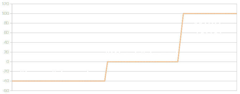
Thanks to algebra, we can directly synthesize both the main signal (61.25 MHz) and the chroma signal (64.83 MHz) at varying intensities and phases. The program created a table with several “colors” or repeating 1408 bit samples of “sync” “black” white” “red”, etc. Now, at any point in time we can select a specific color out of this table to be transmitted. Voilà. Now, the ESP can control the signal output.
Using a Browser To Get Everything Working
Using the interrupt on the I2S meant we can just plan out the video line we want to transmit and hand it over to the DMA engine to get it transmitted in sync.
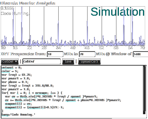
Writing a program to generate these bit patterns then recompiling and re-flashing the ESP took far too long for normal development (Maybe 30 seconds between each test). Instead, since the ESP has a web interface, why not leverage it? By writing a Web Worker, I could write code in the browser which is shown above. With every keystroke it would execute my updated code, creating new bit patterns, run DFTs against them and automatically update the table on the ESP which would start using them to transmit immediately. Milliseconds between development cycles.
What’s up with the funny patterns?
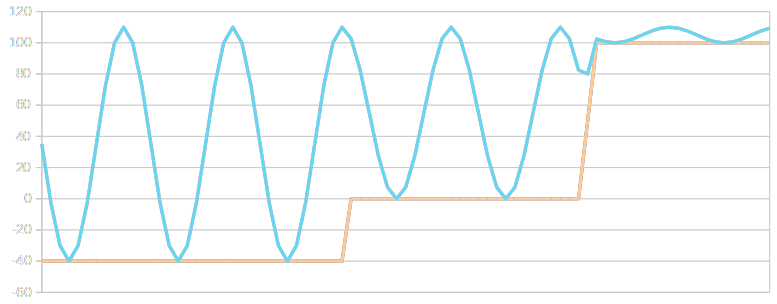
One thing you may notice when having large splotches of colors is that they aren’t really flat and pretty, but rather grainy. This all boils down to the mechanism of our signal generation being so terrible. NTSC Broadcast is analog, not 1 bit changing at break-neck speed.
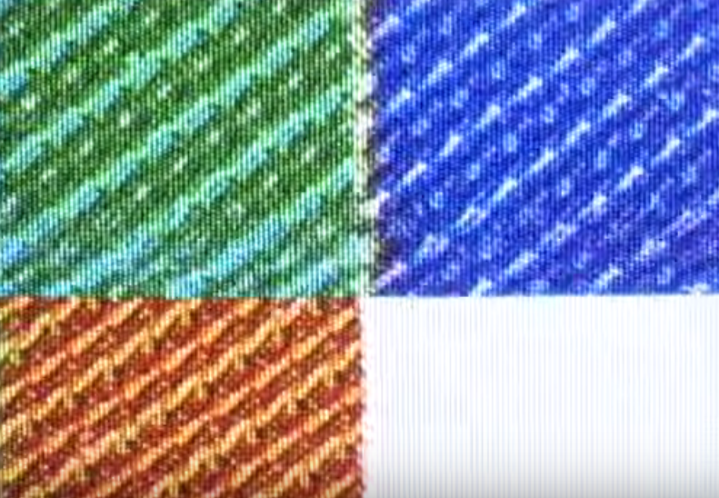
Instead of the television taking a snapshot of 1408 bits and computing averages over that, it’s taking small snapshots and processing the video on them, otherwise our pixels would be a quarter the screen’s width. Because the TV is only looking at a small window (approximately 1us) and the process of outputting 1 bit for our video is inherently random, the signal is rough. When we sample only 60 samples instead of 1408 in the DFT, we begin to see what the TV really sees and just how awful the signal is. The peaks shift around and change in amplitude, resulting in the artifacts the picture above shows.
Where to from here?
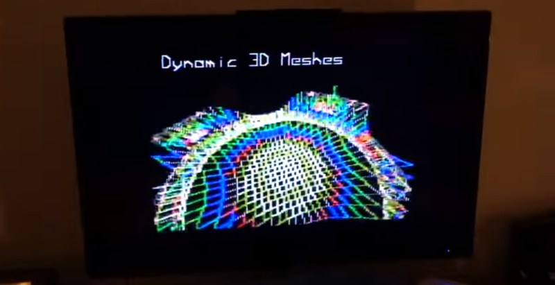
There is some overhead associated with the process of using this table and outputting a framebuffer. The table is only 3kB but the framebuffer is 12kB, a sizable chunk of the ESP’s memory. On the CPU end, I found that it took approximately 10% of the CPU to update the DMA and output the framebuffer. This allows for a great deal of time for drawing the frame itself. Systems could be implemented that calculate the frame on the fly, only store a text buffer, etc. This opens the door for a great deal of performance that could be used for everything from an information text display to drawing sophisticated 3D environments.
NTSC is probably my favorite standard. Its surprising robustness, ubiquity, and simplicity provides the ability to output, transfer and view video in so many ways it hardly matters that the standard is “dead.” Whether a composite plug or broadcast over channel 3, it provides a mechanism for video output to processors large and small. Whenever thinking about what project to do next, don’t forget that there’s grandpa NTSC over there, and he still has got some tricks up his sleeve.
All of the source associated with this project is available on GitHub, and if you missed the video embedded above, here’s another chance to watch the demo.


I saw the picture and title, scanned the article for [cnlohr], until I noticed that he actually wrote it… muaha :) awesome stuff!
+1 I did the same …. Everytime I see something unbelievable that I couldn’t have thought of before, its [cnlohr] :D
Awesome article! How are you getting the FFT with the RTL-SDR dongle? Just put the antenna close to the wire?
It’s NTSC Broadcast. Even picks up the signal a few feet away!
Amazing! What a project, & so well written up 10/10!
Even here in the EU, I’d go for NTSC colo(u)r. PAL, while vastly better, is much harder to generate!
great stuff
Just heads up some newer TV do not like 240p signal. This is what early computer and game console used, doubled every field rather than proper odd/even field so it is always one line short of NTSC frame. This esp8266 hack is doing 240p as well.
It’s actually doing full interlaced 480i on wire. I just happen to be using the same buffer point for both.
It isn’t a hack, it is “The Hack”. This guy is a Black Ninja!
Woz would be proud. This brings back memories of the NTSC generating algorithms on early Apple and other PCs from the 70s.
You might want to look at Bandpass Delta-Sigma digital analog converters.With 80 Mhz “Samplerate” you got 40 Mhz Bandwidth but your signal only needs 6 Mhz. The amount of quantization noise depends only on the number of bits used, the more bandwidth/samplerate you use, the amount of noise per Hz is reduced. Normally the quantization noise is spread equally over all frequencies. Because you use 40 mhz bandwidth, only 6/40 of the quantization noise power is actually within the 6 Mhz of your real signal. But you can do even better: bandpass delta sigma converters reduce the quantization noise by moving most of it to frequency bands outside of your signal band. This is called noise shaping.
Have you tried sending on TV channels 2 or 4? Does that even work at all? If they did, did they work better or worse than channel 3?
They kind of work, but channel 3 is best because it lines up perfectly with the 1408 table size. Maybe if I use a different sized table?
Right, channel 3’s carrier alias at 18.75 MHz requires a buffer that’s a multiple of 64 long, while channel 3’s chroma alias at ~15.17MHz requires a buffer that’s a multiple of 1408 samples long.
In comparison, channel 2’s carrier alias at 24.75MHz and channel 4’s carrier alias at 12.75MHz both require a buffer that’s a multiple of 320 long, and channel 2’s chroma alias at 21.17MHz and channel 4’s chroma alias at 9.17MHz both require buffers that are a multiple of 7040 samples long.
You pose an interesting point. If I didn’t care about color, the tables could be tiny.
These is insane. You are a hacking god!
Wouldn’t you have way, way more bandwidth if you just did this as a composite signal instead of generating RF?
That said, generating an RF signal from an I2S port like this, is of course genius, and a mad idea for a hack. But I bet you’d do much better with native NTSC. Maybe with a small capacitor on the output to smooth out the signal a bit?
Now this is a hack! This for video + more powerful microcontroller for the brains, battery, piezo speaker, case from a dead C64 = completely wireless old school computer that transmits the video wirelessly to your TV?? I don’t have the knowledge to do it but I bet it would be fairly easy for somebody here
can you stream a movie? :)
bad apple on this would be something.
sweet!
this guy is the very definition is a mad scientist.. if i had a dumptruck full of cash i’d just park it outside his house.. this guy is pure awesome.. please keep up the awesome work!!!!!
This _is_ modulation of the overtone at 80Ghz..
Mhz…
Cool, but every time I read about linear RF coming out of a digital port I cringe. The Funny Cookie Company (USA) does too. As a ham I know something about harmonics and I play harmonic flute as well. Wired is better anyway. The FCC never approved TV radiators, unlike with radio.
One of the brightest minds on the planet. Very impressive, and again and again.
This is absolutely brilliant. Excellent work :)
Excuse me while I pick up the pieces of my mind after it blew…
Hard to imagine someone can do all that on such a tiny little chip and even with all the cool interfaces to control it.
This is both fascinating and *really* well-implemented. Amazing work.
Watch both videos. The first one is great, but he really smashes through the looking-glass on the second. CNLohr, you are a mad scientist.
So you must run a composite cable from the I2S pin? What is the max rate of the ESP in its normal operation? So really any MCU with I2S could be used to transmit NTSC, presuming it maintained a real-time rate. What about making it wireless with an antenna- is that a thought image on the thought bubble over yo head?
o.O it is transmitting wirelessly. I am not sure what you mean.
oh I thought you plugged in a composite cable. Wow, the television antenna picks up the signal just from the ESP8266 I2S pin with no antenna? What is the range the ESP8266 can be from the television?
Does anybody happen to know the max speed of the ESP8266 in normal operation- I thought that it might be the max speed of 802.11b/g/n (54 Mbps) but some web sites are saying only 2.8KB/sec. The real value of a cheap WIFI module would be to send 30fps video, and what you have done is possibly one way of doing that- so that’s awesome.
It is transmitting in this video about 15 feet using a wire antenna attached to the I2S bus pin. I’ve been able to transfer about 300kB/sec. Probably could do more if needed.
What kind of wire antenna?
and what voltage – does it need to be higher to transmit farther?
Just a wire slumped over, and it’s at about 3V p-p, dunno what you’d boost it to or if you’d use a real antenna :-/
ok wow- that simple- thanks for the quick reply- really amazing project!
Wonder if the ESP32 improved performance would make this even more stable….