It’s a fair assumption that the majority of Hackaday readers will be used to working with electronic components, they are the life blood of so many of the projects featured here. In a lot of cases those projects will feature very common components, those which have become commoditized through appearing across an enormous breadth of applications. We become familiar with those components through repeated use, and we build on that familiarity when we create our own circuits using them.
All manufacturers of electronic components will publish a datasheet for those components. A document containing all the pertinent information for a designer, including numerical parameters, graphs showing their characteristics, physical and thermal parameters, and some application information where needed. Back in the day they would be published as big thick books containing for example the sheets for all the components of a particular type from a manufacturer, but now they are available very conveniently online in PDF format from manufacturer or wholesaler websites.
Datasheets are a mine of information on the components they describe, but sometimes they can be rather impenetrable. There is a lot of information to be presented, indeed when the device in question is a highly integrated component such as a DSP or microprocessor the datasheet can resemble a medium-sized book. We’re sure that a lot of our readers will be completely at home in the pages of a datasheet, but equally it’s a concern that a section of the Hackaday audience will not be so familiar with them and will not receive their full benefit. Thus we’re going to examine and explain a datasheet in detail, and hopefully shed some light on what it contains.
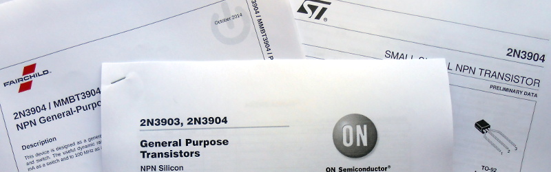
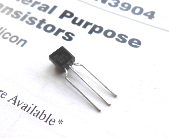
The device whose datasheet we’ve chosen to put under the microscope is a transistor. The most basic building block of active semiconductor circuits, and the particular one we’ve chosen is a ubiquitous NPN signal transistor, the 2N3904. It’s been around for a very long time, having been introduced by Motorola in the 1960s, and has become the go-to device for a myriad circuits. You can buy 2N3904s made by a variety of manufacturers all of whom publish their own data sheets, but for the purposes of this article we’ll be using the PDF 2N3904 data sheet from ON Semiconductor, the spun-off former Motorola semiconductor division. You might find it worth your while opening this document in another window or printing it out for reference alongside the rest of this article.
Let’s take a look at all the knowledge enshrined in this datasheet, and the engineering eye you sometimes need to assign meaning to those numbers, diagrams, and formulas.
Give it to Me Straight
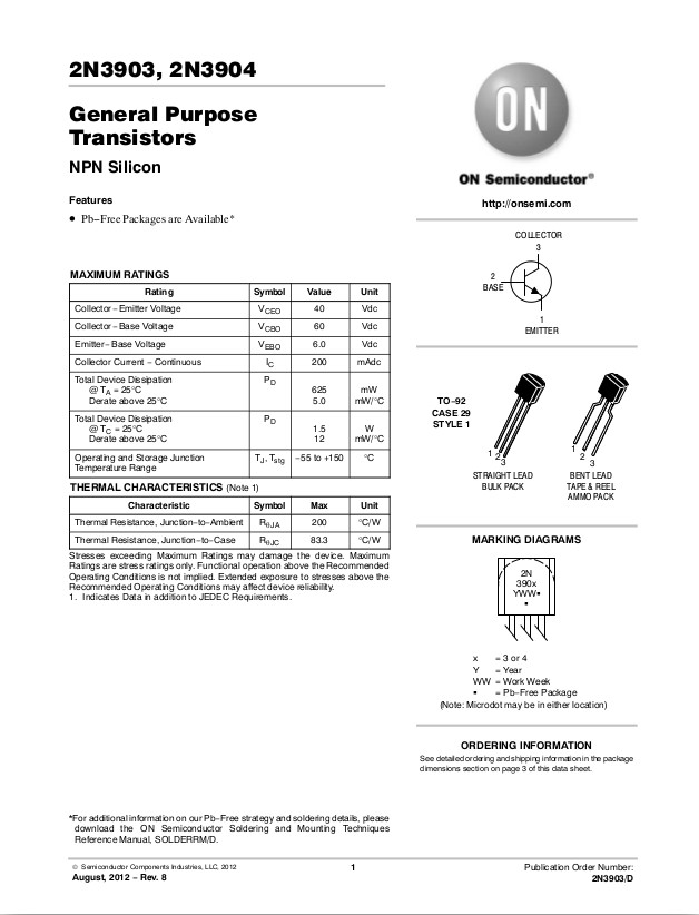
The front page of a data sheet will have the information the manufacturer considers to be most important. This should include the basic electrical properties of a device, a succinct description of what it does, and assuming it is not a device with a myriad pins, information about its external connections. Unfortunately some manufacturers seem more driven by marketing considerations than technical ones, so from time to time you will find data sheets whose front pages feel more like sales brochures, leaving you to have to hunt through the pages for the most basic of information. Happily the folks at ON Semiconductor seem to have a good understanding of what an engineer really wants from the front page of a data sheet, so straight away you have a table of the 2N3904’s maximum electrical ratings and an identification of its external connections.
In the case of a transistor, that table of maximum ratings is probably the single most important set of information for the designer in the whole sheet. You may have special requirements for which you need to know more about the device, but these are the most fundamental parameters that tell you a lot about what the transistor is suitable for, and those that (should you ignore them) can result in it releasing its inner store of magic smoke and costing you the price of another transistor. These are the voltage, current, and power dissipation figures you will have in front of you when you calculate the DC bias circuit for your application, in order to ensure that you’re operating the device within its electrical capabilities.
You needs these when you are selecting a device, for example if you are building an audio amplifier you might be interested in the device power dissipation for an idea of how much power it might be capable of delivering to a loudspeaker. In the case of a 2N3904 you’ll see that after allowing for the heat dissipation inherent to a transistor operating in a linear mode it can only yield a few hundred milliwatts, so a more powerful transistor might be a better choice as an audio power amplifier.
I Want All the Data
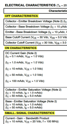 Turning the page, on page 2 of the datasheet we find a much more comprehensive table of parameters for the 2N3904. Off characteristics, on characteristics, small-signal characteristics, and switching characteristics.
The off characteristics relate to the device in the off state, which is to say when the voltage between base and emitter is below the roughly 0.7 volts required to start current flowing between collector and emitter. The breakdown voltages are the same ones that were in the table of maximum ratings on the previous page, they are the maximum voltages a 2N3904 can take before it is damaged. The cutoff currents though are different, they release no magic smoke, instead they are the tiny currents that still flow even when the transistor is turned off. You’ll notice they are measured in nA, nano-amperes, a very tiny figure indeed.
What is an ‘h’ Parameter?
![The h parameter model. User Rohitbd [GFDL or CC-BY-SA-3.0 ], via Wikimedia Commons](https://hackaday.com/wp-content/uploads/2016/04/h-parameters.gif)
The collector-emitter and base-emitter saturation voltages are the voltages at which those connections are at maximum forward bias and will go no further in terms of voltage. The base-emitter path, and the collector-emitter path when the transistor is in the on state can both be considered as though they were forward biased diodes. One of the properties of a forward biased diode is that the voltage across it remains nearly constant no matter the value of the current flowing through it, and it is that constant voltage which is being referred to for the two paths through the transistor. If you think a constant voltage might cause the transistor to cease amplifying though, think again. The bipolar transistor is a current amplifying device, so once the junctions are at their saturation voltages the current flowing in the collector will still be hFE times that flowing in the base and amplification will still occur.
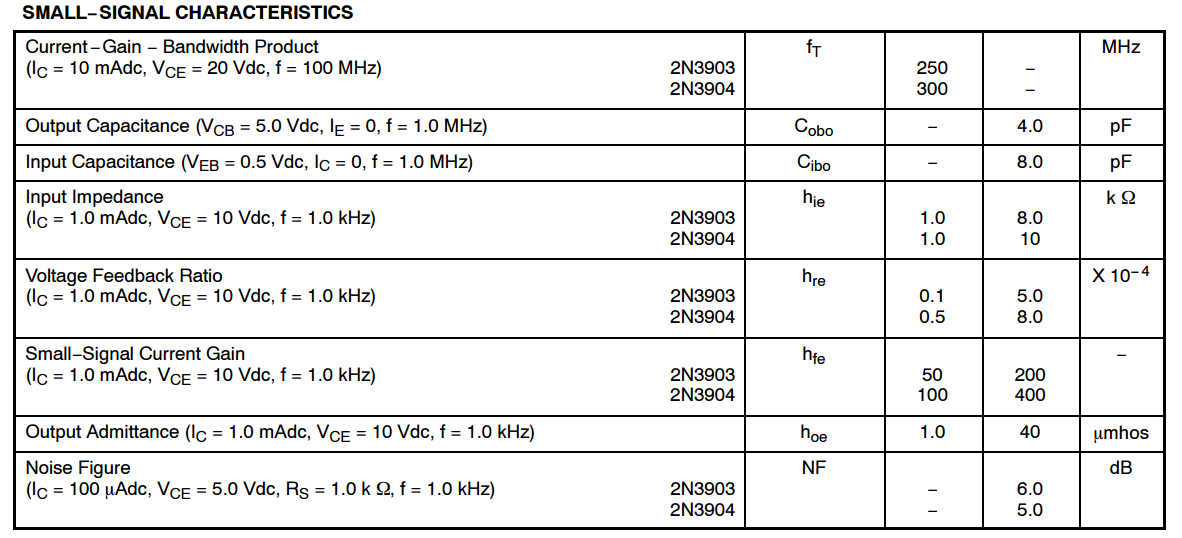 The small-signal characteristics relate to how the transistor performs as an AC amplifier. First up is the gain-bandwidth product, fT. It might be tempting to think that since the fT of a 2N3904 is 300MHz that the device might be usable up to that frequency, but this is a misleading figure. In fact it refers to the frequency at which the gain drops to 1, so the likely maximum frequency at which the device is useful will be considerably lower. In the case of a 2N3904 you would find it to be useful somewhere beyond 100MHz, for example.
Below the fT figure are the capacitances of the different parts of the transistor which will probably be of little importance in the majority of applications, followed by the rest of the h parameters. Again these are likely to be of little interest unless you are putting a 2N3904 into a modelling package. You will notice hfe, the small-signal AC counterpart of the DC hFE we mentioned earlier.
And finally in this section we have the noise figure. This is not a figure that will trouble you in the majority of applications but it is worth taking a moment to consider. If you are working in an environment in which noise considerations are important – perhaps a radio receiver or a demanding audio application – you will need to pay close attention to ensuring that this number is as low as you can make it in particular in the early stages of amplification. In this case the 2N3904 with a 5dB noise figure is not a particularly low-noise transistor, but then again it’s a general purpose workhorse rather than a high-performance thoroughbred.
How Well Does It Switch?
Below the small-signal characteristics is a table of the switching characteristics. If you imagine a perfect square wave, you might imagine it would appear on your oscilloscope screen as a sequence of sharp right angles. Every transition should be instantaneous from low to high voltage. In practice of course it doesn’t work that way. it takes a short time to traverse the gap. These are the parameters that give you those timings, and ultimately that tell you what the fastest logic signals a 2N3904 can handle are. You’d play close attention to these if you were designing fast logic circuitry, but for simple DC or analogue use they would not be something you’d need to know.
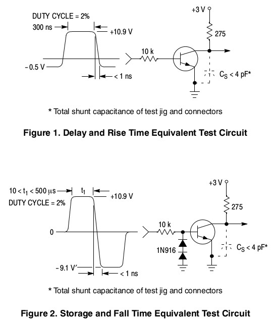
On page 3 of the 2N3904 datasheet you’re into the really irrelevant stuff for most Hackaday readers. Surprisingly, in many sheets this page would be further towards the back of the bundle. Ordering information, something that will interest you if you are buying ten million 2N3904s from ON Semiconductor, but since you are likely to get your transistors from a stockholder like RS, Farnell, Mouser, or DigiKey this section has little relevance. Below that are the circuits used to measure the switching characteristics, yet again something of great interest to a designer using the device in fast logic circuitry but not so gripping for others.
The next three pages have all the transistor’s parameters expressed as graphs. Now you might think that this would be the main event of a datasheet, and in some sheets you’d be right, but in the case of a transistor sheet it’s all very interesting in an Art of Electronics kind of way but you don’t need to bury yourself in them. You already know the pertinent information surrounding a 2N3904 from the first couple of pages, these graphs fill in the edge cases and tell you in more detail about how the device behaves. Fascinating if you are learning about how transistors work, but in most cases of straightforward transistor design you will not gain much from studying them.
And finally at the back of the datasheet, the package information. You’d expect the ordering information to be here too, but for some reason ON Semiconductor put that on page 3. Package information is something you might not consider important, however if you are creating a PCB you may find yourself spending a lot of time in this part of a datasheet. If your PCB CAD package doesn’t already have the device in its library you may have to create it. Even if there is a CAD footprint you had better ensure the dimensions match the part you are sourcing. It is the dimensions on this page that will ensure you get it right. If your device is surface-mount you will usually find a recommended area for its PCB lands with full dimensions, something that can save you a lot of trouble with wrongly-dimensioned boards.
Beyond this Datasheet
We hope this piece has helped demystify the manufacturer datasheet for you if you were intimidated by them. It’s a shame we only have a Hackaday article in which to cover this topic, for if we had looked at all the graphs in detail this would have made a decent sized book chapter. The 2N3904 is hardly an accomplished device, but with luck you’ll now know a little bit more about this most basic electronic building block.
Since we feel that the information contained in electronic component data sheets is often buried and not always fully understood, we’d like to feature more articles like this one. The example here is a transistor, but there is no reason why any of the other devices we use every day could not also be explored in depth, analog ICs, digital ICs, even passive components. Which devices would you like to see given this treatment? What are some of your favorite quirks and tidbits from other datasheets? Let us know in the comments below, and send in a tip for future articles.


I have ones from all over the place. That’s well said.
Great Article – I personally think that reading and understanding datasheets is critical to being able to competently design electronic circuits. I would like to see an article covering reading and understanding FET parameters…mostly because I seem to always get that wrong!
^ I second this.
+1 on this. A FET is a FET is a FET…not. I recently took a new position at a company that designs large current power supplies and they have a ‘guru’ that knows FETs inside and out and although I am towards the end of my career, I am getting all the knowledge he can give me.
He is pushing 80 and loves his job and they love him. I’m 30 years his younger, but we love to leave a 45 record adapter on a newbies desk with a sticky note that says ‘age’ test.
We talk about “Muntzing” a product…
https://www.youtube.com/watch?v=69yXg9EkD-g
… If my mind and soul wouldn’t be so atrophied. I’d have something to say. As it stands now in our PC/SJW world this fellow would be called a “neckbeard” and I could not say a damn thing about his promoting his awesomeness.
Not to mention the “spruce goose” http://www.evergreenmuseum.org/the-spruce-goose
Should make everyone realize they are living on the wrong side of “TomorrowLand”. Ironically bought by Disney/Jobs/Apple/Whim Corp and have made all the Pupshaw species extinct.
Talk about 1st world problems; not allowed to “be” only want they want you to “be”. What a crapsack.
Hmmm..
Not sure what he would add on top of:
http://kidbots.com/WEBADD/HYDROGEN_FUEL/slup169.pdf
It covers the miller plateau and most common drive mechanisms. Only thing missing for Laszlo’s article is the fact that the discrete “fast turn on / fast turn off” circuits create a large di/dt loop that will increase RFI generation and need careful consideration of PCB layout.
Probably the failure modes of MOSFETs:
https://www.fairchildsemi.com/application-notes/AN/AN-9067.pdf
Is he big on SiC and GaN parts, despite their cost?
http://www.onsemi.com/pub_link/Collateral/NTP8G202N-D.PDF
http://www.infineon.com/dgdl/Infineon-IJW120R100T1-DS-v02_00-en.pdf?fileId=db3a304341e0aed001420353f03a0e4b
I’m 40. FYI, I keep hearing that EE’s are unemployable above 40.
Gain-bandwidth product is literally what its name implies. For a 300MHz GBW, you can get up to 30 times gain at 10MHz.
For viewers in Europe, this is about the American version of the BC547. :-)
===Jac
Modern data sheets are a godsend.
Pfft…see my comments below…
Fantastic article!
One thing I slightly disagree with:
“Below the fT figure are the capacitances of the different parts of the transistor which will probably be of little importance in the majority of applications…likely to be of little interest unless you are putting a 2N3904 into a modelling package.”
It’s helpful to at least know that input capacitance (Cibo) is what largely determines “how well does it switch”. Smaller capacitance, faster switching.
Now you might say, why not just look directly at the switching characteristics in the datasheet? It’s true that looking at timing in nanoseconds is far more straightforward than modelling the base of a transistor as a RC network. But consider this scenario:
You have a digital transistor circuit prototype using a common part like a 2N3904. And you need it to switch 2x faster, without changing the input impedance or circuitry. So you go to the parametric search of your favorite parts vendor to find a faster transistor.
But those searches don’t include all the parameters. The lesser used parameters, even if searchable, are more likely to be missing or incorrect.
Cibo is listed before switching parameters for a reason, being more of a primary parameter. And so it’s also more likely to be in your search. If it is searchable, and you know about its relation to switching speed, then you’ll find what you’re looking for without too much trouble.
Else you’ll be stuck opening datasheets for random parts, until you eventually stumble across one that fits the bill. Having done this, I can say it’s a good way to waste a few hours.
I like to put transistors into a spice simulation and swap them out comparing responses. Use the data sheets to select a part from the main parameters then refine that list in spice where all the capacitances and more obscure parameters are tested.
Spice is garbage in garbage out…
google bob pease spice article. ‘Nuff said. He was an ANALOG GOD! LOL…
now now, troll urself elsewhere
Not a troll – Spice is an excellent simulator, but it is literally garbage in, garbage out. I.e., any simulator is only as good as the models it uses, and a lot of “Spice models” given in datasheets reflect wishful thinking.
Wait, wait, wait!
You forgot the absolute most important part of the datasheet. Pretty much should be the first thing you look at after opening it. Don’t even bother looking at the performance ratings until you look at this part.
“Absolute Maximum Ratings.”
Many a project has been thwarted because a part that looks absolutely perfect just happily blows up or burns because the parts weren’t rated to what they were exposed to. Or worse, the project works fine, for a while… until the magic smoke comes out.
And right after that…
Absolute minimum ratings…
Because that’s why your “300” gain 2N3904 doesn’t work in a circuit that actually needs a gain of 300, like in an emitter follower with an improperly chosen bias resistor. Because suddenly the gain goes to 25.
Another interesting characteristic would be the temperature dependency of the transistor’s parameters. Its how specifically a 2N3904 can be used as a temperature sensor.
Another interesting characteristic would be to analyse “matched pair” transistors that are the same 2N3904, but created with the same process and now the two transistors will closely match each other’s parameters and temperature dependencies. Now they’re nice to use in a current mirror application such as a cheap high side current sensor front end.
But since this article is about datasheets, keep in mind SMT parts usually include a Rtheta-junction-case and Rtheta-junction-air power dissipation characteristic that is critical. MMBT3904 for example. Gets really important when you move to SOT-523-3 and SOT-723-3 footprints.
Minimal pad layouts are critical. These are described in the datasheet and should be verified against your PCB library.
It might also be of interest to use a tool that extracts data from datasheet nomographs:
Something like this:
https://sourceforge.net/projects/graphdataextrac/
V helpful article. Now I have read it, I can see the same basic layout in other data sheets and am comforted that I’m not missing much by not bothering to read to the end! Thoughts that struck me after reading this:
– similar articles on other components would also be helpful for noobs like me. +1 for MOSFETs, regulators, even diodes, capacitors and other basics;
– once you’ve learnt what to look for, you still have to find a component that’ll work from the thousands that are out there. Are there any web resources to help you find the right one? The large suppliers allow you to filter by some basic characteristics, but not necessarily the ones that you need to dig into the data sheets to find. I’ve got friends who seem to be able to instantly recall part numbers of suitable components, and maybe one day I’ll be able to, but in the meantime it’d be great if there was something to help;
– some of the vocabulary is still a bit baffling. Opening a datasheet at random, it describes the component as ‘monolithic’ having outputs that are ‘low-side, open-drain DMOS transistors’ and ‘Avalanche Energy’ of 30mJ. No idea what all that means – what I know at the moment is that it’s a shift register and it works in my circuit. I’ve tried searching for definitions of those sort of terms, and have found nothing but long paragraphs containing yet more technical terms. How about, in the same spirit as your article, a Hackaday Dictionary containing just what you need to know in Plain English?
When you were talking about the hFE and the collector current being 300mA is that current always 300mA regardless of load? Sorry for my noobness.
As long as the collector-emitter voltage is above a few tenths of a volt, the collector current should be around 300 mA. But notice that this is *only* true for a transistor with a hFE of 300. In practice, you should never make your designs dependent on a particular precisely defined value of hFE, as it varies widely with collector current, collector-emitter voltage, temperature, etc., etc. — not to mention that transistors from the same batch can easily have hFEs that differ by a factor of, uh, five. One way to go about that would be to find out the minimum guaranteed hFE of the transistor you are going to use (easily found in the datasheet as hFEmin, derate by 20% or look up the graph of hFE vs. collector current to be sure) and then design your device so than any transistor with any non-inferior gain will do.
Nice, thanks for that.
Not quite correct. When the transistor approaches saturation, the current gain goes down. Note in the datasheet page pictured that with Vce of 1V and Ice of 50mA, 5mA of Ibe is specified.
If you need a big minimum gain, think Darlington.
If you need a big minimum gain with less than 2x Vbe drops, think Sziklai.
“Pillaging” holds a slightly different connotation to me, so I didn’t expect a (fine and useful) article on simply reading the datasheet.
If any other readers are similarly confused, here’s my favorite method of pillaging datasheets: open the PDF in Inkscape (renders one selected page at a time), and break/ungroup to copy and paste graphics, dimensioned footprints, performance graphs and more into your own vector graphic designs!
A great tip! Thanks very much!
Excellent article. Maybe a follow-up about the gotchas in most datasheets (where marketing department blow up maximum power/current ratings with dubious test methods for example) and maybe derating rules? (ie don’t use your component beyond 50-70% of their maximum rating)
Here is my take now that I will soon be going into my 30th year of having a job that I can’t explain to most people…lol.
30 years ago, guys in suits drove station wagons because they were electronic companies representatives. You needed a part. You knew what you wanted, you gave them a call, described what you wanted, they came to see you, and gave you data books. Yes, books, those funny analog thingies that smell bad when they get old. They don’t upgrades, they don’t have an HTTP link. Books…now whay would I bring this up?
Plain and simple, there is a blue and a brown book from Motorola that covers the 78 series regulator. Two hundred plus pages. Quite a page turner. How does 200+ get down to about a 12 page data sheet? It isn’t the fantabulous radio shack schematic shrinking device, it is because at one point, engineers got paid to write books on devices.
Then came the bean counters who looked at that engineer and said he wasn’t required. I have seen and fixed simple little products that have a 78 series regulator in them that oscillates and the product has a RF circuit and they beat against each other. A Motorola or a Fairchild would work but an NJR would not.
A 78 series thing is so simple. DC in -2V overhead, well, we’re done! Not so fast…
And this is where most data sheets now suffer so badly. There isn’t enough information. The original 78 Series data book shows the schematic of exactly what is inside of the funny black thing that will emit ‘magic smoke’ if pushed too hard. Bypass caps, type and size are discussed.
What happens when it gets cold or it gets hot or fill in the blank. Old data books hold a plethora (hmm…good ghetto name for a kid… Sorry not PC) of wealth.
They don’t write .pdf data sheets like they used to. In fact, .pdf files are nothing more than a snapshot in time. Sometimes, data sheets are misaligned scans from one company to another, with the 78 series being a great example.
I bring this up for a very simple reason. A good data sheet, I can look at it, read it, see several examples of how to use it and not waste my company’s time and the semiconductor’s time making a…gasp PHONE CALL or an email (that mostly gets unanswered).
Data sheets today are nothing like they used to be. I was involved in a lawsuit where a large net was cast and the product involved had a micro, that the micro company said would wake up from sleep mode in 6 clock cycles, when it actually took 12.
Code was written to 6, it took 12, the company (and the engineers) walked away free and clear. The micro company which will remain anonymous due to records being sealed was held liable. This is why a minimum amount of information is given and a statement written in lawerese is now on every data sheet.
I only bring this up, because I know this is a hacking site, but if you, like I enjoy immensely what you do, you would want to pass on this knowledge. Then again, when sitting in a bar, what are you more likely to hear? How about them (fill in a sports team name) or, “Hey are you designing anything using component X?”
I know of several micro companies that when they find a guru using their products will snipe those engineers and employ them as app engineers.
To hackaday? Well…when an engineer that is pushing 50 applies, maybe you should think about employing that person. After all, I fixed the problem with your Teddy Ruxpin…
You didn’t hire my Dad who was next door at DAC. Secondly, I didn’t get the gig at Sega at 17 (in my prime). Thirdly Xerox was next door.
What a play out, next door DAC build smart meters. Ivory tower Ruxpin a-holes. FYI that Triangle/Hexagon Bot was lame looking. Like a ‘tarded ET.
i bet that old 78xx book is available as a pdf somewhere..
Well said.
Yes, I was trained in the data book era :)
I would argue that a lot of that information still exists, but split into data sheets and application notes. For example earlier today I was looking at a common mode choke from Wurth. Nice piece of kit, but the data sheet was only part of the story. The app note by comparison was a book chapter in itself and covered the whole topic. It helped guide me to the exact choke for my application, and made the sale.
200+ pages on the 78xx?
Sounds like management picked what sounded like an impressive number, then demanded someone fill it, regardless of whether it was done with useful information. I imagine the same process is responsible for quality articles like “50 Sex Tricks That Will Change Your Life”.
It’s possible I might be wrong about the specific book you describe, but I’ve seen some of these old and massive tomes. They are mostly filled with numerous and impressive schematics. Ff you happen to want a complete schematic to build a polyphonic organ, a power supply for a copper vapor laser, an analog computer, or one of dozens of other very specialized devices, then hooray, it’s your lucky day! But chances are you don’t, you just want a regulator circuit for something of your own design, so all that is quite useless. It’s included under the mere technicality of having at least one 78xx somewhere in each schematic, and contributes nothing to your understanding of the part the book is actually supposed to be about.
The really important information is summed up in far fewer pages. Forrest Mims taught many of us all we needed to know about a part in page or two. True, some datasheets omit things they really shouldn’t, leading to much frustration. But things like your example of bypass caps, type and size, do not need to be discussed in every datasheet. Instead that is more properly covered in a separate app note or book, because that information applies to every standard-dropout linear regulator in existence.
Also, if your design requires intimate knowledge of the schematic inside the IC to function, it seems to me you’re designing quite specifically and close to the limits. Back in the day, I suppose you could justify that; those limits were often restrictive, the parts expensive and infrequently changed. These days, it’s not a fair risk. You’re just setting yourself up for failure when the part is revised, manufacturing process changes, you select an equivalent part from a different vendor, an unexpected transient occurs, or the published limits are optimistic. And with that I will step off my soapbox, composed of the growing hill of electronics I’ve repaired or thrown out due to failed low-ESR caps; all because the designers decided to be clever or save a few cents, instead of providing a large operational margin!