In our previous issues in this series on making circuit boards, we covered placing solder paste and placing components. Now it’s time to bake our cake!
There are a variety of methods for reflowing a circuit board, but they all rely on a single principle: heat up the solder paste (a mixture of flux and solder) until the flux burns off and the solder becomes liquid, and then cool it down. Accomplishing this once or twice is easy; once you’ve played with a hot plate you’ll swear off through hole. Scaling it up and doing it repeatedly with high yield is extremely challenging, though.
Hot Plate
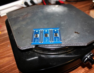
Starting off with the most basic tools available we have the hot plate or griddle method. This involves an electric hot plate ($20 investment). Usually around medium heat is a good setting for most of these plates, and you know it’s ready when you can put some solder on it and it turns to liquid. Then you place the board on the hot plate and wait and watch until everything has flowed, then wait a little longer until most of the flux has burned off, then you take it off the plate. Generally you want to move the PCB around with tweezers or needle-nose pliers during this process, as there will usually be hot spots and you want everything to flow at roughly the same time. DO NOT use the fancy science hot plates with the magnetic stirrers in them. When the paste starts to flow the reduced friction will allow certain components, especially inductors, to fly across the board as they are attracted to the magnet, causing a hot mess. It’s also helpful to have a piece of wood or metal to transfer the PCB to after reflow, as it will be very hot and you don’t want to set it down on a kitchen counter. Finally, I like to have a 1/4″ aluminum plate on top of my hot plate to even out the temperature and provide a smooth surface. Another neat trick is to place a small chunk of aluminum or other metal on top of the hot plate and reflow only a certain section of the board. This is particularly useful if you need to remove a microcontroller from an already assembled board but don’t want to reflow the whole board.
This process can be quick; only a couple minutes for the board to reflow completely. The downside is it requires constant attention, and unless you are doing something else to preheat the boards, you’re not putting them through anywhere near the proper temperature profile, meaning that they may develop stress fractures as they cool, or the flux won’t burn off completely. Other long term issues may crop up in higher volumes. Still, it’s a personal favorite.
Hot Air
Graduating up in equipment is the hot air method. Here you would use a hot air rework station and carefully wave it over the PCB until it reflows. Don’t hover too long over any particular part as it could burn, and don’t get too close or the air might blow it off the pads. Really this method is only good for a few boards at most. It’s time consuming and tiring to hold, and the rework station is really only meant for rework, not whole boards.
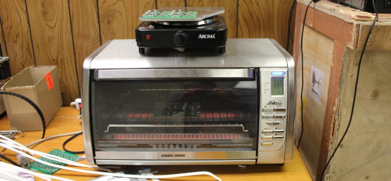
Toaster Oven
The next level is the toaster oven, and beyond that is the toaster oven rebuild. Most toaster ovens are capable of getting to 450F, which is right at the top of the reflow profile for lead free solder, meaning it’s possible for leaded as well. It’s important that convection takes place, so there needs to be a fan that’s running inside to circulate the air, and the elements need to be capable of ramping up the temperature fast enough. Some toaster ovens are underpowered and can’t get hot enough fast enough, meaning the flux will burn off before the solder flows, and then it does not flow well at all.
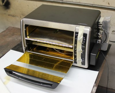
Some people like to make minor modifications to the oven (like bypassing the wiring for the fan so that it’s always on) and then just use quick settings like “frozen treats” to approximate a profile, and this works if you will be babysitting and watching for it to flow. Others go the automation route, removing the electronics or other controls and putting in PID controllers and thermocouples so that a consistent reflow profile can be had. Now it’s just a matter of putting the PCB in, pressing a button, and waiting for it to finish. Since the top of the toaster oven is usually very hot, it’s a good surface for preheating the next boards or cooling the just-finished ones.
Tabletop Oven
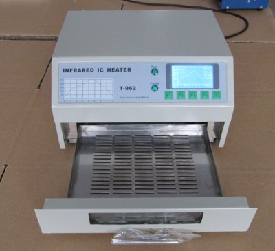 Now we are getting into the professional equipment, and the first kind is the desktop reflow ovens. The most common one among hobbyists and small businesses is the T962A. It uses IR as the heating method, meaning dark parts heat up faster. It also has air flow and usability issues, which is why there’s a secondary market for new controllers and upgrades for this machine (which we covered).
There are other models available, but they’re hardly better than the modified toaster ovens. If you don’t want to futz with modifying a toaster, but you don’t have the space or volume, then the desktop reflow oven is ok, but it’s difficult finding a good one.
Conveyor Zoned Oven
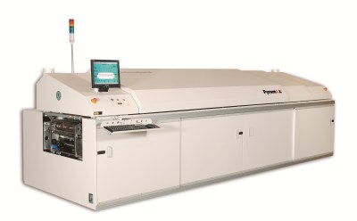
The factories use reflow ovens with conveyors and multiple heating zones. Just like the fancy pick and place machines have a conveyor that takes in PCBs on the left and spits them out populated on the right, the reflow ovens connect up to the pick and place output and convey the PCBs through the oven, with each heating zone representing a different part of the reflow profile, spitting cooled and completed boards out the other end. Having zones means a continuous operation takes place and it doesn’t require constant monitoring by a person, plus the machine doesn’t have to waste energy heating up only to try to dump all that heat at the end of a single cycle. Keep in mind, though, that these machines are typically in the $100k and above range, and occupy space the size of a car, in addition to pretty hefty electricity bills.
Other Considerations
Do not use these tools for food afterwards. Neither lead nor flux is healthy. Also make sure you have adequate ventilation, especially if you are doing lead-free work. Again, the flux.
There are a few factors that make repeatability challenging, and some ways to design boards to get around them. Ever wonder why thermal reliefs exist on pads that are connected to pours? It’s because it makes soldering easier and more consistent, and if two pads flow at different times then it can cause something called a tombstone, where the component sticks on one side but not the other and sticks up vertically.
Paste is a huge variable, and people can have wildly different results based on what paste they use. The stencil is extremely important as well, as different aperture size and stencil thickness means different amounts of paste dispensed, which means more likelihood of bridging when there is too much solder. The ramping speed/profile is useful to know as well, especially when you are doing things like the hot plate where you have to eyeball the profile. The reflow stages include the following steps:
- Preheat – Warm up the board from room temperature to 150C. For a minute or two.
- Soak – Let it hang out below the melting temperature for a minute or two. This dries out the board and gets everything to an even temperature. If parts are hotter than others, then the solder won’t flow evenly and tombstones are likely.
- Ramp – Bring it up to the reflow temperature and let it hang out until all the solder has flowed and the flux has mostly burned off. This should take about a minute.
- Cooldown – Once it has peaked and everything has flowed and the flux has burned off, cool it down fairly rapidly but not too fast. If you hear crackles as the board cools, it’s cooling too fast and tiny stress fractures are happening. These fractures have the potential to break joints or even the components themselves. This should take about a minute.
Try to match that and you’ll be fine.
Reflowing is a fun experience when you can watch as the paste turns from dull gray to shiny silver, and all the components float and snap into place. It’s surprisingly easy and forgiving in small batches. Give it a shot!


I modified a non-convection oven a few years ago with an Arduino-based temp controller and a solid state relay; it worked decently well but had a lot of hot spots. I recently bought a nicer convection toaster oven and it’s great as-is; I just set it to 205 C, make sure the fan is on, and hit the start button; four minutes later (while the oven is still technically in ‘preheat’ mode) I just cancel the run and prop the door open about a half inch to cool at a reasonable rate. I’ve done about 200 boards this way with zero issues, usually 15-20 at a time. Controllers are nice since you don’t have to worry about setting a 4-minute timer, but they definitely aren’t necessary if you have a decent oven!
What oven did you buy?
I got the fancy KitchenAid model they had at Target, I think it was $200ish (but I needed it _that day_). You could probably get away with a much cheaper model as long as it’s a convention oven.
I built one with a kit from here: http://whizoo.com/ The thing works fantastically. The extra heating element in the kit seems to help quite a bit. I just used the Black and Decker toaster they recommended, mostly because someone was offering pre-made aluminum shelves for it.
Toaster ovens are easily found at your local thrift shop in the 5-20 dollar range. I’ve tried re-flow with a unmodified convection oven and it works great (only did about 5 boards, but 100% positive experience).
http://burnt-traces.com/?s=reflow&searchsubmit=Find+%C2%BB
Cool, I figured the convection feature was only on “high end” toaster ovens (quotes because seriously how much could you possibly spend on these simple devices). I’ll have to take a look and see if I can find a used one. I purchased a simple reflow station last year which has been great, but if you have a lot of components it takes a long time to populate a board. I’d like to move on up to an oven.
Mine is a B&D toaster oven with 1 top element and 1 bottom element. It costs around $20 new. I wouldn’t bother with the used one in that price range unless it has dual top elements. More top elements means that the heat would be a bit more even.
I have only modified the mechanical stop for temperature setting limits so that the upper limit can reach 260C. Other than that no electrical modifications.
Mine is the older brother of that. It was a 70s model, probably cost more than $20 new because of “new” and “fancy” factors. So far, it’s reflowed parts off of several old motherboards into the parts bin (seriously those are great value for all the SMT parts you can get) and turned an old evil slot mount AMD cpu into a book mark. After that proof (it killed the AMD CPU, even fire had failed at that previously), it did a bit of solder reflow on an Arduino motor board that I had stressed too much; didn’t need to touch it with the iron at all.
Cost me only $5, since I found it at a yard sale. Separate top and bottom heating elements, with controls that work either one or both (turn it one way up to get just 1, upside down to get both) and has good enough temp control that I could dial in the preheat, soak, and final temp, and get from soak through ramp in less than 5 minutes by hand. Still, if I ever find a cheap thermocouple and PID, and time, I’ll automate the oven.
I got much better results with ovens of this kind: http://www.ebay.com/itm/DENI-QUICK-N-EASY-CONVECTION-OVEN-MODEL-10100-/291779700178?hash=item43ef6ce5d2:g:lWwAAOSw71BXQJ5~
The thermal mass is much lower, thus it is much easier to get proper temperature profile.
Interesting, I never those kinds of ovens being used. I think they work with halogen lamps, do you have issues with black components being heated more than the rest?
I’ve only tried it a few times so far, no overheating problems observed yet.
BTW, this was my source of inspiration: http://andybrown.me.uk/2015/07/12/awreflow2/
My controller is slightly different (it’s basically relay/thermocouple interface with USB interface – I always have some PC in my workshop, and implementing fancy UI seemed like a waste of time to me), but the oven is pretty much the same and it works great.
I have found that there is a sweet spot for thermal mass of a hotplate vs. Wattage where a 1/4″ aluminum plate sitting on the surface with the boards sitting on it allows for doing a preheat, soak, reflow, cool cycle where the boards go in cold with the hotplate cold and you do the preheat and soak by twiddling the thermostat knob on the hotplate and keeping an eye on the boards. Also, a hotplate with a glass lid can be useful (mine is a rounded-rect shaped electric wok / deep skillet w/ glass cover which I use for the preheat stage, YMMV.
It often helps a toaster oven heat up faster and more evenly if you line the inside with aluminum foil – especially if it’s old and has accumulated grunge on the inside which cuts down on the reflectivity. You may also wish to permanently wire all the coils to be on, to prevent accidental changes via the oven controls.
I had to insulate my toaster oven on the outside with rockwool (except for the door and the underside). Otherwise, temperature was ramping up too slowly. Now it is almost perfect. Like zakqwy above, once soldering is done I open the door a bit to promote cooling at the recommended rate.
Hot spots on a hotplate are easy to avoid – put the PCB on top of a 1mm-2mm layer of sand. If you do it inside a glass-lidded saucepan, then there will also be some heating by convection.
Finally, using gas enables the temperature profile to be controlled easily.
I’ve got gas! Lol.
Never heard of the sand idea. I would think that soldering circuits and abrasive particles don’t mix well. But I’m thinking it over. ;)
Components on both sides would be interesting with sand. If I needed to do that I would experiment with supporting the PCB on standoffs just above the sand.
Use a non-contact directional thermometer to see how fast the temperature is rising. I’ve documented my experiences here: https://entertaininghacks.wordpress.com/2015/03/25/assembling-pcbs-with-surface-mount-components/
“Don’t hover too long over any particular part as it could burn, and don’t get too close or the air might blow it off the pads. Really this method is only good for a few boards at most. It’s time consuming and tiring to hold, and the rework station is really only meant for rework, not whole boards.”
I tend to use a hot air rework station a *lot* more than a typical soldering iron, and really, I think the difficulties you’re talking about here are more problems with a specific rework station you might’ve used rather than the idea. Doing an entire board with hot air is certainly faster and a hell of a lot more reliable than hand soldering it.
Reflowing it using a reflow oven is lots faster than that, but there are advantages to piecemeal assembly – you can test the parts of the circuit as you go, and for QFN parts, with hot air you can immediately *fix* a component since you’re watching it while it reflows – so using a rework station is very forgiving with how much paste you put on. You can also tap the component to make sure it’s actually held in alignment under tension, too. (None of these are terribly helpful for BGAs, obviously, but I have a lot more no-lead parts on boards than BGAs).
I’ve never had a ‘burn’ problem (the air’s only 250-270 degrees C or so, and obviously the component never gets that hot or else it’d reflow). Components blowing off pads can be a problem, but that’s why you start with a very low air volume and raise it once things start to reflow.
Most of the sub-$1K rework stations sold are pretty crap – the reason your hand gets tired is because the hot air tool is way too heavy and awkward.
A follow up article on what to look for with choosing/using solder paste; and storing, handling it could be good please. I’m getting good results in my oven usually, but not sure if I could be doing better and avoiding rework just through better choices with the paste.
I would definitely bookmark that article. I’m still not very good at soldering. I didn’t realize how important flux really was until about two years ago. I was just using the same roll of non lead for everything. (Through-hole mostly.)
I just found some desoldering tips on HaD while writing this. Apparently I skipped a few weeks!
Probably not. It’s probably more to do with non-uniform heating in the oven, the stencil itself, or the mask , in reverse order of likelihood. If you don’t have a mask dam between pins, it’s just going to be unlikely to reflow perfectly all the time.
You might also want to see if you can avoid leaded parts (as in, QFPs, or 0.5mm/0.4mm SSOPs) in favor of no-lead (QFN/DFNs/etc.). Tight-pitch QFPs are probably the hardest components to reflow perfectly, and I can say from experience that even *assembly* companies don’t get it right 100% of the time. Almost all of the shorts I’ve found from professional assembly have been on tight-pitch leaded parts.
QFNs/DFNs/BGAs/etc. pretty much reflow perfectly if you get the placement right and have the right volume of solder laid down with the stencil. The other ‘gotcha’ there is to make sure you reduce the size of the stencil opening for an exposed pad.
Why use hot plate/oven instead of a hot air gun/rework station?. I prefer the hot air approach especially when i need to solder parts to both sides of the board
Can you use a laser cutter to melt solder paste? Calibrate it to deliver just enough energy to get a good join and nothing more? It seems like the fastest way to do it if the laser has line-of-sight to all of the pads (not always the case I know), without any risk of over heating any other part.
When using a laser cutter for *anything*, you have to know *exactly* what will happen to the stuff that is heated and where it will end up. In this case that includes heavy metals and who-knows-what in the flux.
Now, will those “combustion” products end up coating lenses, or being deposited in someone’s lungs/fingers or on their food?
Ah, yeah not that level of power obviously, you want to melt it and nothing more. Can’t that be calculated?
I put the word “combustion” in quotes to hint that burning isn’t necessarily involved. Consider that you have to dump sufficient energy into the components and PCB to raise the temperature sufficiently. With an oven that is done from all directions across the entire surface, whereas with a laser it would be done with a small spot.
I suspect it would be difficult to calculate, because you would have to make assumptions about the materials, their thermal conductivity, their specific heats, and the thermal diffusion – for all the different geometries involved. Calculations might get you in the right ballpark, but then you would have to do practical experiments.
I’m sure lasers could be used, and probably are for a few well-tuned specialised industrial processes including spot-welding. But beginners/experimenters should always be aware of what they don’t know.
But you knew that :)
Yup some science will be required, but a few gradient test should narrow down the parameters. The variables are perhaps less than you suggest though, the paste has a constant composition and thickness if it is squeegeed on. then track widths as a discreet set of values. Length is effectively constant as it is limited by the maximum thermal transmission for the very short period of heating. A 2D grid of past blobs on one axis and track widths in the other should allow you to then expose the blobs to a range of energy quantities. Then you’ll have a line of good weld that is a combination of the right amount of heat for the track width, assuming width is a relevant thermal wicking factor.
There are so many “ifs” there that *calculation* will be difficult.
Amateur (for that is what we are considering) paste thickness will be variable. Consider ground planes. Consider nearby vias, thermal and otherwise. Consider components: connectors with large leads, QFP ICs, leadless QFN ICs, 1206 vs 0402.
I’ve no doubt that it *could* be done, but I strongly doubt that it is practical for an amateur, and I don’t see any unique benefits.
Most of that may not matter because the rate of thermal transfer could be low enough compared to the speed of the laser shot needed to optimally melt the solder paste. See what I mean now? More power over less time makes thermal conduction less relevant. I’ve use gradient methods on high temperature vs component mix type combinations before, you can divide an conquer the problem if you have a lot of variables, to map out the parameter curves. For example if I have 3 variables with a division of 10 across their ranges I first test a 10×10 matrix for A and B then take the 10 values that work from AB to test against 10 values of C. That is 200 test rather than 1000. See how it works?
That’s only conjecture. The details are critical.
I can’t “see how it works”, because it hasn’t been demonstrated. I can see how you guess it might work.
OK can we quantify it? The rate for copper would be the fastest of all the materials involved, so what sort of pulse times would we need from a typical laser cutter to raise an area under the beam to 188 °C There are a few hints here that may help nail it down, http://alumni.media.mit.edu/~yarin/laser/physics.html
If you want to add numbers, do so. But don’t forget to add *all* the numbers for all the variations. And then *safely* do the experiments to validate numbers.
What are all the numbers? I can see that under shooting is not a safety issue, that will just give you a bad weld. Overheating is what you are worried about, right? Rosin fumes are as bad, but not worse than plastic as both are hydrocarbons and their complex breakdown products. So if you cut plastics and account for those fumes you are covered. The metal depends on what you use, I’d assume these days it is lead free, so a tin-antimony mix or tin-silver-copper, tin boils at 2602 °C and antimony at 1635 °C, the others are even higher. So metal fumes are not likely, it is not like the issue with welding anything with zinc in particular, but even that is 907 °C.
What did I forget?
A little knowledge is a dangerous thing. Based on your current statements, I can assure you that you don’t understand all the hazards.
It would be foolish of me to try to educate you in this forum, since it would end up being a half-baked (ho ho) education – and therefore dangerous.
Lair, you actually know SFA about the subject, we worked that out several comments back, fool.
Pro tip; don’t use an induction hot plate.
“once you’ve played with a hot plate you’ll swear off through hole” That’s me!
Has anyone tried a “sandwich toaster” for this? The kind that you fold shut?
I searched Google for awhile; I wanted to see it!
I found nothing for waffle irons or standard toaster technology. If anyone did, I think it may have been a failure. :(
Used a heat gun feeding into an old bust toaster oven using thermocouple and a PID control loop. This way you get convection, and a rapid decent as cooler air can be fed in.
Cheap simple, a little noisy though.