Reverse Engineering The OWON SDS7102 Oscilloscope

It is something of a rite of passage for an electronics enthusiast, the acquisition of a first oscilloscope. In decades past that usually meant a relatively modest instrument, maybe a 20MHz bandwidth and dual trace if you were lucky. Higher spec devices were eye-wateringly expensive monsters, not for the Common People.

We are fortunate that like most other areas of technology the world of test equipment has benefited in the last few years both from developments in digital technology and from the growth in Chinese manufacturing. If your first ‘scope is that second-hand 20MHz CRT you will probably secure it for pennies, and the first ‘scope you buy new will probably have a spec closer to those unattainable super-scopes of yesteryear. Gone is the CRT and timebase generator, in its place a TFT, system-on-chip, and super-fast A to D converter.

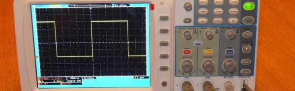
[Christer Weinigel] has just such an entry-level modern digital ‘scope, an OWON SDS7102. He comments that it’s got an impressive spec for its price, though the input is noisier than you’d expect on a more expensive device, and the software has one or two annoying bugs. Having owned it for a while, he’s now subjected it to a lengthy teardown and reverse engineer, and he’s posted his findings in a succession of blog posts.

[Christer]’s interest lay mainly in the OWON’s digital section, it seems there is already a substantial community paying attention to its analog front end. He’s deduced how its internals are connected, ported Linux to its Samsung SoC in the scope, succeeded in getting its peripherals working, and set to work programming the Xilinx FPGA that’s responsible for signal processing.

The series of posts is a fascinating read as a run through the process of reverse engineering , but he points out that it’s quite a lot of information. If you are just interested in how a cheap modern oscilloscope works, he says, he suggests reading his post in which he recaps on all its different components.

He also makes a plea for help, he’s no slouch on the ‘scope’s software but admits he’s a bit out of his depth on some aspects of the FPGA. If you’re an FPGA wizard with an interest in ‘scopes, he’d like to hear from you.

This isn’t the first time we’ve featured ‘scope reverse engineering here at Hackaday, though it may be more in-depth than others. In the past we’ve seen a Uni-T screen grab protocol laid bare, and an investigation of a Rigol 1054Z.

Taming The Beast: Pro-Tips For Designing A Safe Homebrew Laser Cutter

Homebrew laser cutters are nifty devices, but scorching your pals, burning the house down, or smelling up the neighborhood isn’t anyone’s idea of a great time. Lets face it. A 60-watt laser that can cut plastics offers far more trouble than even the crankiest 3D-printers (unless, of course, our 3D printed spaghetti comes to life and decides to terrorize the neighborhood). Sure, a laser’s focused beam is usually pointed in the right direction while cutting, but even an unfocused beam that reflects off a shiny material can start fires. What’s more, since most materials burn, rather than simply melt, a host of awful fumes spew from every cut.

Despite the danger, the temptation to build one is irresistible. With tubes, power supplies, and water coolers now in abundance from overseas re-sellers, the parts are just a PayPal-push away from landing on our doorsteps. We’ve also seen a host of exciting builds come together on the dining room table. Our table could be riddled with laser parts too! After combing through countless laser build logs, I’ve yet to encounter the definitive guide that tells us how to take the proper first steps forward in keeping ourselves safe while building our own laser cutter. Perhaps that knowledge is implicit to the community, scattered on forums; or perhaps it’s learned by each brave designer on their own from one-too-many close calls. Neither of these options seems fair to the laser newb, so I decided to lay down the law here.

Continue reading “Taming The Beast: Pro-Tips For Designing A Safe Homebrew Laser Cutter”

The Citadel Is The King Of K’nex Builds.

Following one’s passion can lead to amazing results. Sometimes this results in technological marvels; other times, one marvels at the use of the technology. An exemplary display of the latter is The Citadel.

Over the course of three years, redditor [Shadowman39] pieced together this monstrous K’nex structure. With over 17 different paths(!), 45 different elements, and over 40,000 parts, you would expect some meticulous planning to go into its construction — but that’s not the case! [Shadowman39] assembled it largely on the fly with only a few elements needing to be sketched out and only the main elevator proving to be troublesome. Three motors power the structure — one for the main elevator, one for the smaller lifts on the bottom, and one for the release gates.

This is an absolute leviathan hobby project. To satiate the obvious curiosity of anyone who stumbles across this picture, its intricacies can be seen in the video:

Continue reading “The Citadel Is The King Of K’nex Builds.”

Automating A Microscope For CNC Micrographs

[Maurice] is a photographer specializing in micrographs. These very large images of very small things are beautiful, but late last year he’s been limited by his equipment. He needed a new microscope, one designed for photography, that had a scanning stage, and ideally one that was cheap. He ended up choosing a microscope from the 80s. Did it meet all his qualifications? No, but it was good enough, and like all good tools, capable of being modified to make a better tool.

This was a Nikon microscope, and [Maurice] shoots a Canon. This, of course, meant the camera mount was incompatible with a Canon 5D MK III, but with a little bit of milling and drilling, this problem could be overcome.

That left [Maurice] with a rather large project on his hands. He had a microscope that met all his qualifications save for one: he wanted a scanning stage, or a bunch of motors and a camera controller that could scan over a specimen and shoot gigapixel images. This was easily accomplished with a few 3D printed parts, stepper motors, and a Makeblock Orion, an Arduino-based board designed for robotics that also has two stepper motor drivers.

With a microscope that could automatically scan over a specimen and snap a picture, the only thing left to build was a piece of software that automated the entire process. This software was built with Processing. While this sketch is very minimal, it does allow [Maurice] to set the step size and how many pictures to take in the X and Y axis. The result is easy automated micrographs. You can see a video of the process below.

Continue reading “Automating A Microscope For CNC Micrographs”