This one’s not a flashy hack, it’s a great piece of work and a good trick to have up your sleeve. Sometimes you’ve got a voltage difference that you’d like to measure, but either the ground potential is at a different level, or the voltages are too high for your lowly microcontroller.
There are tons of tricks with resistive voltage dividers that you can play. But if you want serious electrical isolation from the target, there’s only one way to go — an optocoupler. But optocouplers only really transmit digital signals, and [Giovanni Carrera] needed to measure an analog voltage.
Enter the voltage-to-frequency IC that does just what it says: produces a square wave with a frequency that’s proportional to the voltage applied. Pass this square wave through an optocoupler, and you can hit one side with voltages approaching lightning strikes without damaging the microcontroller on the other side. And you’re still able to measure the voltage accurately by measuring the frequency on the digital I/O pins of the microcontroller.
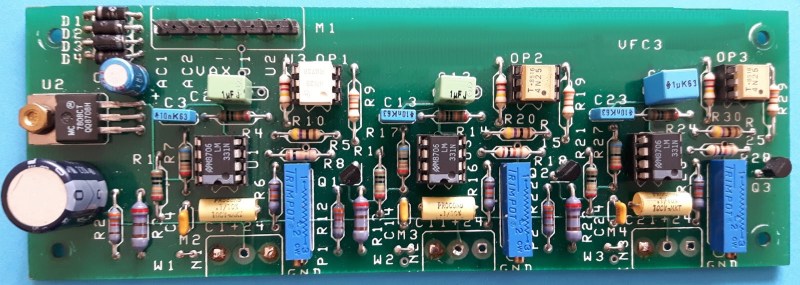
[Giovanni] built up and documented a nice circuit. He even tested it for linearity. If you’re ever in the position of needing to measure a voltage in a non-traditional way, you’ll thank him later.


If you are wondering about the amount of parts: the picture is for a 3-channel version.
This is a brilliant idea! I have been pondering off and on how to safely use a µC to measure voltage without toasting them. This might just be what I would need to make that work.
You can also stick a small uC with an ADC on the primary side to transmit binary data (e.g. async serial) through an opto.
That’s what I use a lot. Or you can keep primary side “dumb”, usage modern components enables you to make it even simpler – you can use MCP3301 or some of other SPI ADCs (or perhaps sigma delta ADC) and ADUM1401 or similar isolator. Along with DC/DC converter and decoupling caps it’s something like 6 components for complete isolated ADC channel, giving digital data.
The solution with LM331 is nice, though it needs further processing (frequency counter).
SPI ADC requires at least 2 optos if not 3. If you want to convert multiple channels, then the number of opts goes up and you would also need multiple timers inputs on the other side to read off the frequency.
The lower end $1 microcontrollers (e.g. ARM) comes with 12-bit ADC are very price competitive with stand alone ADC chips. They come with internal timer for sampling rate, analog mux and can scan multiple analog channels. You can off load some of the processing e.g. averaging there too. With async serial, you would only need 1 opto to send out the data. Having to program yet another chip in the system is a pain though.
Opps. The multiple timers are for V/F. I meant multiple SPI for receiving the SPI ADC. There are minimum SPI clock frequency on these SPI ADC as they also use it for the internal conversion clocks, so bit-banging might not work too well.
You can always just tap the circuit driving the needle coil in a $15 analog multimeter with a MCU’s ADC , if you don’t need such a sophisticated solution.
The LM331 is a great chip, designed by the legendary Bob Pease. Resolution and linearity are very good; better than you’re likely to get with a micro with internal A/D. Be sure to read his application notes to get the most out of it (National Semiconductor AN-210, AN-240, LB-45; EDN magazine March 20, 1978, Electronic Design magazine Dec 6, 1978). There are tricks in the choice of components that those not familiar with analog design may not know.
I used the LM331 for a similar application; see http://www.sunrise-ev.com/balancer.htm. The circuit diagram is at http://www3.telus.net/nook/balancerland/balancer/rev_b/BControl_e.pdf. It has two channels, to measure an isolated voltage and current. I included an opamp to buffer and level shift the input.
Old times HP instruments did this a lot, the 5300A System display (Top) was always a frequency meter, while the bottom could be an multimeter, frequency counter.. etc, works like a charm
In the 80s I used this trick to transmit several physiological data channels plus an audio track on a single audio channel for telemetric monitoring and recording. Each monitored parameter (ECG, temperature, EtCO2, SP02, blood pressure…) got its own subcarrier in the 4-7 kHz range, and the data were extracted by a running FFT, all perfectly synchronized with the communications audio track. It worked fantastically well, extremely portable, and could be used at a variety of sites with limited connectivity between the test site and the monitoring location. It even worked with cassette tape. These days I might go all-digital and maybe even radio, but this blew away other alternatives at the time and was very quick and cheap to make.
> But optocouplers only really transmit digital signals
Wut? Uh…… no. Every switch-mode power supply you have is using an optocoupler in it’s analog regime. They’re not too *linear* in their analog regime, but if it’s in a feedback system with enough gain, that can be ignored.
No, Switch mode power supplies commonly use a zener shunt and operate the optocoupler in its digital state
1) optocouplers linear region is unpredictable and changes with temperature (a big nono in SMPSs)
2) i have yet to stumble onto a switching converter with the opto feedback being anything but a digital input
Actually, a well-designed output voltage control loop should use the opto in the linear region. Where you see a Zener shunt (cheap & cheerful, nothing wrong with it) you will almost always see a series resistor as well. This gives a small voltage range with linear feedback:
I_LED = (V_OUT – V_Z – V_LED) / R_s
I_PD = k I_LED
You are certainly right that the current transfer ratio k will move a lot with temperature and ageing. This is why better control loops have something like a TL431 shunt regulator. It provides a bit of local gain which can dilute the effect of variations in k.
If you design it wrong, the system will certainly exhibit hard on/off behaviour, but this is not the desired mode of operation.
All that being said, I once tried to use a normal onto as a linear transfer element and the results were not pretty. Only really useful for small peturbations, AC coupled.
There are special optos like the HCNR200 which have a second photodiode explicitly for closed loop control of LED current, and they can be very linear (0.1% or better) with reasonable DC accuracy. Does require more circuitry though.
http://www.avagotech.com/cs/Satellite?c=AVG_Product_C&childpagename=AVG2%2FAVG2_Layout&cid=1206562914565&packedargs=d%3DTouch&pagename=AVG2_Wrapper
There is actually an opto made for passing analog signals. It has two identical photodiodes and you use one of them for a feedback circuit on the driver side (primary side) to linearize the device.
http://www.avagotech.com/products/optocouplers/industrial-plastic/specific-function/high-linearity-analog/hcnr201
FYI: http://www.eetimes.com/author.asp?section_id=36&doc_id=1325778
“Power Tips: Compensating Isolated Power Supplies” by Brian King, Texas Instruments
The article shows how the feedback loop works with the math and everything.
They do make linear optocouplers but they are generally more complex and expensive
i have done this in power supplies with unfiltered class D amplifiers before … works quite well!
The trusty IL300, or equivalent linear photo-coupler
http://www.vishay.com/docs/83708/appn50.pdf
…
Dual matched optos is in the same package, which means CTR will track between the optos and temperature drift.
Set up as a current mirror.
Gets you an isolated voltage meter.
…
This is quite an old-school approach – technology is starting move in a different direction. They are not very cheap (unless you are buying by the million) but you are starting to see isolated ADC chips appearing – ADC plus isolation built in – this is being driven by the energy metering market – this will give 14 to 16 bits ENOB with a couple of kV of isolation. Also now that there are digital isolators with built in isolated DC-DC converters you can stick a nice ADC and perhaps a micro to perform scaling and compensation on the isolated side. Cost is getting to be competitive with a discrete analogue approach.
Here’s a nifty chip I found in a Nissan Leaf charging board, the ACPL-782T Automotive Isolation Amplifier. Typically used for isolated current monitoring. $10 in single quantities, but discrete solutions add up fast as well.
http://www.avagotech.com/products/optocouplers/automotive/isolation-amplifiers/acpl-782t-000e
“But optocouplers only really transmit digital signals”… Say what? There are many optocouplers specifically designed for ANALOG signals, from couplers using phototransistors, (still in fairly frequent use as the feedback / isolating component in switching power supplies), to old-school photoresistive couplers used in older electronic instruments, such as ‘legacy’ audiometers. In fact, it’s pretty safe to say that the first optocouplers were analog. “Digital Only” indeed!
It’s almost 2019, and Avago has turned into Broadcom. But they still make the whole line of HP low-speed fiber optics. I’ve used them for 20 years for isolation in high power transmitter equipment. They use plastic 1mm fiber which you can cut with a razor blade and it usually works, or you can polish the end with 600 grit sandpaper. The LEDs are red, so you don’t need an optical pyrometer to see if your fiber is broken or your LED is bad. As long as you keep the Rx/Tx in a faraday cage you can isolate millions of volts and high RF. AFBR-2521 is one receiver part, listed under Industrial Transmitter receivers. They’re $13 so pricey for say auto use, but you’d think something similar would be used in cars to send data around instead of copper.