
The pioneering years in the history of capacitors was a time when capacitors were used primarily for gaining an early understanding of electricity, predating the discovery even of the electron. It was also a time for doing parlor demonstrations, such as having a line of people holding hands and discharging a capacitor through them. The modern era of capacitors begins in the late 1800s with the dawning of the age of the practical application of electricity, requiring reliable capacitors with specific properties.
Leyden Jars
Mica
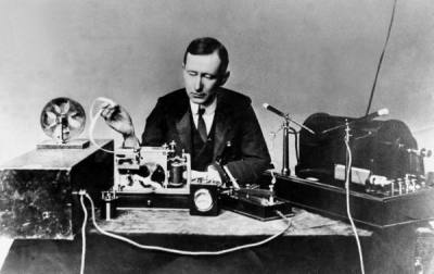
In 1909, William Dubilier invented smaller mica capacitors which were then used on the receiving side for the resonant circuits in wireless hardware.
Early mica capacitors were basically layers of mica and copper foils clamped together as what were called “clamped mica capacitors”. These capacitors weren’t very reliable though. Being just mica sheets pressed against metal foils, there were air gaps between the mica and foils. Those gap allowed for oxidation and corrosion, and meant that the distance between plates was subject to change, altering the capacitance.
In the 1920s silver mica capacitors were developed, ones where the mica is coated on both sides with the metal, eliminating the air gaps. With a thin metal coating instead of thicker foils, the capacitors could also be made smaller. These were very reliable. Of course we didn’t stop there. The modern era of capacitors has been marked by one breakthrough after another for a fascinating story. Let’s take a look.
Ceramic
To get higher capacitance another ceramic, barium titanate was used, as it had 10 times the permittivity of mica or titanium dioxide. However, they had less stable electrical parameters and could replace mica only where stability was less important. This was improved after World War II.
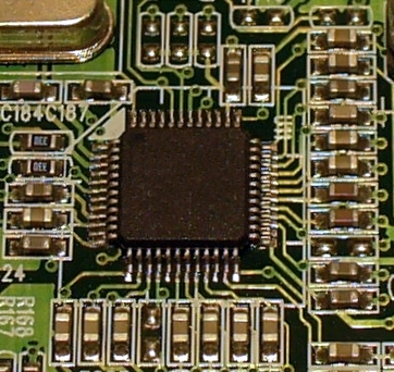
An American company launched in 1961 pioneered the multi-layer ceramic capacitor (MLCC) which was more compact and had higher capacitance. As of 2012 more than 10^12 barium-titanate MLCCs are produced each year.
Aluminum Electrolytic
In the 1890s Charles Pollak found that an oxide layer on an aluminum anode was stable in a neutral or alkaline solution and was granted a patent in 1897 for a borax electrolyte aluminum capacitor. The first “wet” electrolytic capacitors appeared in radios briefly in the 1920s but had a limited lifespan. They were called “wet” due to their high water content. They were basically a container with a metal anode immersed in a solution of borax or other electrolyte dissolved in water. The outside of the container acted as the other plate. These were used in large telephone exchanges to reduce relay noise.
The patent for the electrolytic capacitor’s modern ancestor was filed in 1925 by Samual Ruben. He sandwiched a gel-like electrolyte between the oxide coated anode and the second plate, a metal foil, eliminating the need for a water filled container. The result was the “dry” electrolytic capacitor. Another addition was a paper space between the turns of the foils. All of this reduced the size and price significantly.
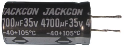
In 1936 the Cornell-Dubilier company introduced their aluminum electrolytic capacitors, including improvements such as roughening the anode surface to increase capacitance. The Hydra-Werke, an AEG company, began mass production in Berlin, Germany at the same time.
After World War II, the rapid development of radio and television technology lead to larger production quantities as well as a variety of styles and sizes. Improvements included reducing leakage currents and equivalent series resistance (ESR), wider temperature ranges and longer lifespans by using new electrolytes based on organics. Further developments from the 1970s to the 1990s also included lowering leakage currents, further reduction in ESR and higher temperatures.
What became known as the “capacitor plague” occurred during the years 2000 to 2005, possibly due to the use of a stolen recipe but without certain stabilizing substances leading to premature failure.
Tantalum Electrolytic
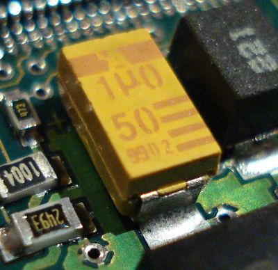
Although Bell Labs made the fundamental inventions, in 1954 the Sprague Electric Company made improvements in the process, producing the first commercially viable tantalum solid electrolyte capacitors.
1975 saw the emergence of polymer tantalum electrolytic capacitors with much higher conductivity conductive polymers replacing the manganese dioxide leading to lower ESR. NEC released their polymer tantalum capacitors in 1995 for SMDs (surface-mount devices) with Sanyo following suit in 1997.
Tantalum ore is subject to price shocks and two such occurrences happened in 1980 and 2000/2001. The latter shock led to the development of niobium electrolytic capacitors with manganese dioxide electrolyte delivering properties roughly the same as tantalum capacitors.
Polymer Film
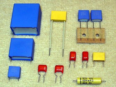
Research in plastic by organic chemists during World War II resulted in this going further. In 1954 the first
mylar capacitor was one of those. Mylar was trademarked by Dupont in 1952 and is a very strong PET (polyethylene terephthalate). In 1954 a 12um-metalized mylar film capacitor was produced. By 1959 the list included capacitors made with polyethylene, polystyrene, polytetrafluoroethylene, PET and polycarbonate. By 1970, electric utilities were using film-foil capacitors without the paper.
Double-Layer (Supercapacitors)
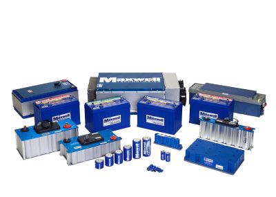
Standard Oil of Ohio developed another version and eventually licensed it in the 1970s to NEC who finally commercialized it under the trademarked name, supercapacitor. It was rated at 5.5V and had capacitances up to 1F. They were up to 5 cm^3 in size and were used as backup power for computer memory.
Brian Evans Conway, professor emeritus at the University of Ottawa, worked on ruthenium oxide electrochemical capacitors from 1975 to 1980. In 1991 he described the difference between supercapacitors and batteries in electrochemical storage, giving a full explanation in 1999 while coining the term supercapacitor again.
Products and markets grew slowly with product names such as Goldcaps, Dynacap and PRI Ultracapacitor, the latter being the first supercapacitor with low internal resistance developed in 1982 by Pinnacle Research Institute (PRI) for military purposes.
Relatively recent developments on the market include lithium-ion capacitors which dope the activated carbon anode with lithium ions. These have capacitances in the thousands of farads (4-digits) at around 2.7V.
Conclusion
Based on your comments in response to our History of the Capacitor – The Pioneering Years post, there’s no shortage of the usage of the term condenser rather than capacitor. So where does the term capacitor come from? That seems to be unknown, but the Oxford English Dictionary quotes from the 1922 BSI (British Standards Institution?) Glossary of Terms in Electrical Engineering that says ‘capacitor’ is a ‘new term’ and suggests it be used to avoid confusion with the steam ‘condenser’.
While that concludes our history of the capacitor, there’s plenty more we’re sure could be added based on the large number of types of capacitors alone. Let us know below if you have any interesting additions you’d suggest. And history being only one portion of the path of progress, let us know of any current or expected future development you’re aware of. What will a Hackaday writer 50 years from now have to say about capacitors today and the coming 50 years?


Hello, I’ve read the article and were left with a simple question. In the beginning of the article is stated about alu. eleco’s “These were used in large telephone exchanges to reduce relay noise.”. So now my questions is why? How does that work? Did they pile them up in large stacks around the relays to form some sort of sound barrier? I’m sure not, but how do you silence a relay with a capacitor.
I do know of ways to reduce the current consumption of a relay circuit, simply put a resistor in series with the relay and place a large cap across the resistor. This way the relay has the power to attract properly (using the load current of the cap) and when the capacitor is full, the resistor takes over and limits the holding current of the relay.
But silencing? Anybody knows any details?
I assume they reduced electrical noise, not acoustic.
Haha, never thought of that, haha. Silly me. I was so focused in my mind thinking about the audible noise of hundreds of relays switching continuously that I did never even realized that they could have meant electrical noise.
It may well have caused acoustic noise… on both ends of the telephone line.
Don’t forget about waxed paper capacitors. They were made of layers of conductive foil and waxed paper, rolled up. They’re found in a lot of pre-1970s electronics, in places where we would now use mylar or ceramic capacitors.
They were large and would become leaky as they adsorbed moisture from the air.
When I was growing up, this is what I pulled out of old radios.
Not often you see the word “adsorb” used in the wild.
Two things about electrolytics.
It seems common that the beginner thinks polarized capacitors are specified, because they see them in the schematics. But I can’t think of anything that requires polarized capacitors. What’s specified is large value capacitors, and the only way to get that, or at least in a reasonable size, is to use electrolytics, which are polarized.
The thing that has changed is that large value capacitors are now more common. In tube days, they’d be filter capacitors in the power supply, maybe audio coupling, and cathode bypass in the audio stages. And they’d be relatively small values. Tubes were high impedance, high voltage at low current, so large value capacitors weren’t plentiful. Finding bad electrolytics was relatively easy, hum in the audio meant a bad filter capacitor in the power, low audio gain likely meant a bad cathode bypass capacitor.
That changed with transistors. Low voltage but higher current, they were low impedance and to be effective capacitors had to be larger value. Even early transistor pocket radios had more electrolytics than the equivalent tube radio. You might see motorboating if a bypass capacitor on the supply voltage had gone bad.
It did mean electrolytics got better, and smaller. I have one about the size of a Coke can, bought surplus bout 1973, it’s 15000uF at about 15V. You can get that in a much smaller package in more recent times.
It got worse later. The arrival of switching supplies meant electrolytics didn’t have to be as large in value, since they were running at ä much higher frequency than the 60Hz in a power supply. And computers and other digital equipment have a lot of electrolytics sitting cross supoly lines that are may see. Lot of high frequency noise. That all puts more on the electrolytics, not seen decades go. The circuitry is more intricate, a bad capacitor maybe not as obvious as in tube radios decades ago.
Michael
There’s another capacitor family not mentioned: varactor diodes. These devices are reverse biased diodes whose capacitance varies by applied reverse bias voltage. They are frequently found in voltage controlled oscillators, especially in older radio and TV front ends. You can purchase a true ‘varactor’ which will have reliable characteristics device to device, or you can try almost any diode – even an LED. The junction capacitance of any diode will vary somewhat with applied reverse bias voltage.
I think I’d classify them as semiconductors rather than capacitors.
But yes, lots of semiconductor junctions will provide the effect, to varying degrees. Though one article decades ago warned about using plain diodes that had a clear casing. He was getting hum in his VCO, until he realized the clear diode acting as a varactor was being modulated by the desk lamp.
Even when Sam Harris described the first practical parametric amplifier in CQ about 1958, he suggested trying other things first, to get a feel for it, before splurging on a then new and expensive varactor.
Michael
Varactor diodes; but not really. ‘Urban legend’, kind of. Really works. Really.
A friend called to ask if I had any small-value (10pf-30pf) hi-freq caps. Seems he needed two to use in the ubiquitous CMOS clock oscillator found in almost every microprocessor/controller, and which typically uses caps in that range (HIS design called for caps of 15 pf and 22 pf. Of course).
To effect a quick fix, I suggested that he use two REVERSE-biased high-frequency signal diodes (1N4148, maybe? 1N914?) in place of the capacitors, as they would probably have capacitance in the range he needed and at the voltage he was using.
It worked; and it works.
(Note: a low-frquency rectifier diode–a la 1N400X–most likely will not work; it’ll just act as a mushy lump. Sorry for all the high-tech talk)
“Sorry for all the high-tech talk”
BAH! HAHAHA!
P.S. *affect :P
To the Editors:
You desperately need to get a higher class of reader, or you are in peril of going the same way as Yahoo!’s “Answers”.
You need to court readers who actually know something, including use of the language.
I wholeheartedly agree.
Interesting read. Would have been nice to get something about variable capacitors in there. From what i understand, they were quite essential in the early days of radio transmission.
And, maybe a bit too far off topic, all the applications where a capacitor is acually used as a direct sensor element would have been interesting too. May it be industrial sensors for process control, or capacitive touch buttons and touch screens…
I’m seconding the variable capacitor omission.
I suspect an article is in the works. :)
And again I am reminded of the time I missed out on 1500 farad supercaps on sale for 6$USD from an online surplus place..
Kicking myself.. Again..
Ouch. They’re only 500F and I don’t know how good they are but a quick search on ebay turned up some very cheap (under $6, free shipping) 500F, 2.7V supercapacitors. Here’s one for $4.76 http://www.ebay.com/itm/1pcs-2-7V-500F-Super-Farad-Capacitor-Super-Capacitor-35-60mm-/182190031303?hash=item2a6b5f41c7:g:5iwAAOSwuzRXdS4I
Very good. I never knew the dates of when the various types of capacitors came into use.
Hi Back to Jan of the 2016 comment.
Questioning how capacitors could be used to silence relay noise.
I suspect capacitors were placed across the switched contact points to eliminate points arcing or transients there when the contacts were pulled open and close by the relay coil. The contacts purpose being switching connections between phone lines. The capacitor reducing clicks and clacks on the phone line.