We toss together our own PCB designs, throwing in a microcontroller here or there. Anything more demanding than that, and we reach for a Raspberry Pi or BeagleBone (or an old Linksys router). Why don’t we just whip together a PCB for a small Linux computer? Because we don’t know how…but [Jonas] apparently does. And when we asked him why he did it, he replied “because I can!”
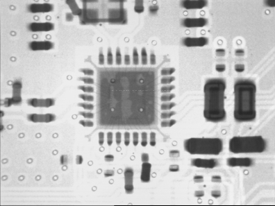
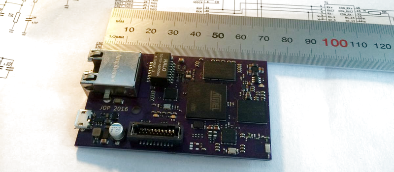
His Ethernet-to-6LoWPAN gateway project is a small, OpenWRT-capable Linux computer in disguise. Rather than yet another Raspberry Pi project, he designed around an Atmel AT91SAM9G25 400 MHz CPU, and added some memory, Ethernet, and a CC2520 radio chip to handle the wireless side. It’s all done on a four-layer board, and hotplate/skillet reflowed. This seems temptingly like something within our reach. [Jonas] had access to X-ray machines to double-check his reflow work, which probably isn’t necessary, although it looks really cool.
When finished, the project will link together a 6LoWPAN network (probably home automation) and his home wired network. That makes this device a rival to something like Philips’ Hue Bridge, which was the subject of some controversy when they locked out other devices for a few days until they recanted. Indeed, in response to this, there’s been quite a lot of effort at hacking the firmware of the Hue device, just to stay on the safe side in case Philips plays shenanigans again.
Soon, that’s not going to be necessary. [Jonas]’s design is open from the ground up, and coupled with open software running on top of the OpenWRT router operating system, that’s the full stack. And that’s great news for folks who are thinking about investing in a home automation technology, but afraid of what happens then the faceless corporations decide to pull the plug on their devices.


Sexy CPU, sexy board. I would double check with X-Ray myself, after hours of developing you have to enjoy the beauty for a bit.
Ok.. this isn’t the first time there have been articles about people x-raying stuff. It seems to be getting more common which got me thinking.. how the …. can there be so many people with their own x-ray machines? So.. I checked EBay. I see dental XRay machines as low as $500. Is that the kind of thing people are using for this?
Building your own linux running board from bare chips is awesome. Me and a fellow student did the same based on the sitara chip from TI. A bit of paste + cheap chinese oven and you can assemble your own pcb’s:
https://dl.dropboxusercontent.com/u/2741941/Forum/hackaday/IMG_20151125_155845.jpg
https://dl.dropboxusercontent.com/u/2741941/Forum/hackaday/IMG_20160120_092532.jpg
Mmm, that’s yummy. Where did u source ure wifi module?
Also, was EMI a concern? you haven’t routed the top layer much.
The module is the WL1801 from TI. Most of the routing is done on the inner layers:
https://dl.dropboxusercontent.com/u/2741941/Forum/hackaday/TheElement.png
We only had a minor conducted immunity issue. We had the shielding of the USB connectors connected to the main ground plane trough ferrite beads. This caused the shielding to lose its function (i didnt knew this). After we replaced the ferrite bead by a 0R resistor we were fine and passed that test. Radiated emission and immunity where fine for “consumer” levels.
Am I mistaken, or is that an 8-layer paste up?!?! Now I see why you didn’t have to route much on the top layers.
(Wow, that’s insane. Do you have this written up?)
I’d love to see a write up too!
If anyone knows a step by step to flashing the required software like u-boot and what not, i’d really appreciate it. designing and building an SBC has been something i’ve been interested in for a while!
Cheers.
Why no metals in that area? Why the strange shape? Good bit of work!
Dropbox does not like the traffic HaD is generating :(. The no metals area is surrounding the WiFi antenna. I experienced the hard way that if you dont explicitly mark it this way the PCB FAB will place copper there since they think its better xD. Thanks! Strange shape is because it needed to fit in an existing enclosure.
Do you have any tips regarding routing the DDR3 signals?
Match the lengths. Run solid planes between layers. Try to get tracks impedance-matched (though that can be tricky unless you have really thin dielectrics between layers). Remember that you can swap pins in data bus groups, but not address pins.
I have to say it has been awhile sense I have used a discreet Ethernet transformer in a project thanks to those magjacks