Cutting out precise shapes requires a steady hand, a laser cutter, or a CNC mill, right? Nope! All you need is PCB design software and a fabrication facility that’ll do the milling for you. That’s the secret sauce in [bobricius]’s very pleasing seven-segment display design.
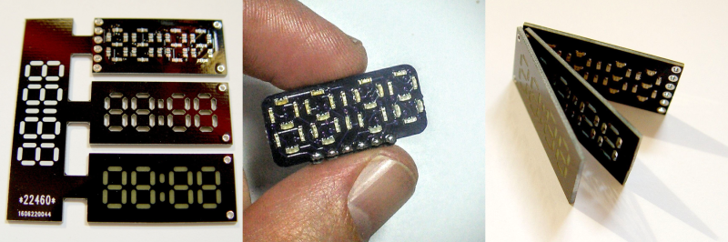
His Hackaday.io entry doesn’t have much detail beyond the pictures and the board files, but we’re not sure we need that many either. The lowest board in the three-board stack has Charlieplexed LEDs broken out to six control pins. Next up is a custom-routed spacer board — custom routed by the PCB house, that is. And the top board in the stack is another PCB, this one left clear of copper where the light shines out.
We want to see this thing lit up! We’ve played around with using PCB epoxy material as a LED diffuser before ourselves, and it can look really good. The spacers should help even out the illumination within segments, while preventing bleed across them. Next step? A matrix of WS2812s with custom-routed spacers and diffusers. How awesome would that be?


No picture lit up? Probably because it bleeds light badly between segments and makes the whole thing unusable.
If it has plated via and slots it could work. However, I’d wager they are better off with 0.5mm pcb for the window mask layer, as it would also be more efficient for lighting.
Getting those holes plated probably wouldn’t cost all that much.
I wonder if just a few moments of black spray paint on the middle layer would be enough to prevent any bleed?
Yeah I suspect that would work perfectly.
I also suspect an issue of total brightness. Charliplexed LEDs don’t have very high duty cycles, and the thick FR4 in the top layer is going to block or reflect a significant amount of the light.
Charlieplexing done correctly is only fractionally dimmer than normal mulliplexing, but yeah if you don’t fit transistors for the row drive, brigtness suffers,
That’s pretty darn cool! Next up: 14 segment version for that retro look ;)
Seven segments are what like 80 cents a piece?
Getting a board house to make anything is most likely going to be in excess of 20 dollars.
Nope. That artwork should fit into dirtypcbs’ 5×5 cm size. In which case it will cost US$14 for 10 copies ($1.40 each). It will definitely fit into the 10×10 cm size, which is US$25 for 10 copies, and you could probably panelise four sets in that space, so about 60 cents each.
http://dirtypcbs.com/
do they do internal routing like that too?
I believe so. For that price (on a two layer board) you can do your own panelisation within the 5×5 cm area, so you can draw your own mousebites and the routed slots between them.
I am hoping to use dirtypcbs for a project soon, so I have been reading all about them. There are a lot of satisfied geek customers doing creative things within the limitations of dirtypcbs’ service.
Thanks for the link I hadn’t seen a board house operating this cheaply.
While being made out of china at such a low cost has me worried, i might keep it in mind for a few projects. ;)
JLCPCB does a 10×10 for $2. They are losing money on that so they hope you come back for bigger batches later. And they give you only one of these super-deals per order, The next board is more than twice as expensive at $5…
But you can do it in any shape you want, 20 USD for a couple of custom front panels is pretty darn great.
I’m glad to see a digital clock display with room for 24hour display
I credit Dave Jones for my use of PCBs as front and rear panels for extruded chassis:
https://www.youtube.com/watch?v=wg_J9WElvBY
Aslo works to just replace the box lid with a PCB:
http://www.wolftronix.com/amc_control/testBox.jpg
Hmmm… Why does it seem to me as if half of the world has never heard of the reverse breakdown voltage led burnout phenomenon and considers charlieplexing without protection diodes a good design…. :(
The current, assuming a high enough reverse voltage (which I’ve never had an LED break down, even with 20VAC+proper resistor on it), is likely refreshed so fast that it doesn’t matter.
Maybe because half of the world has never heard of it.
Please enlighten us, I’m curious (no sarcasm here, I really am curious).
When applying reverse voltage to the LED there is no current, no glow. What kind of burnout of a phosphor can be said?
But with dynamic indication, in order for it to glow noticeably, the maximum impulse current through the LED is several times higher than its passport values.
And the LED differs from the incandescent lamp. He has no inertia. And it turns out that the average diode current is for example 20mA, and the pulse current is 60mA. And this degrades the crystal!
A typical LED is rated for an absolute maximum reverse voltage of 5V. I assume OP is talking about the fact that people assume LEDs will deal with normal diode reverse voltages (the 1n4001 for example is rated for 50V), when in fact it will break if you do that.
The leds are specified to a reverse voltage of 5V. Thus even if you start with a 5V processor, you’re still officially safe as long as the power supply does not wander to 5.5V. On the other hand, things won’t be that critical, so in practice they won’t burn out even at 5V.
I have worked on charlieplexing led stripes a time ago, where it was crucial to reduce wires to a minimum. I faced the problem, that after some time (in my case over two months) of continuous operation on 30% to 50% PWM (reversing voltage) the LED stripe overall lost its luminosity by roughly 70% compared to a new one I finished by that time. So I wondered where there might be a reason and double or triple-checked my design. After talking to several people they brought up, that even if a LED can operate as a diode it will have an effect on the substrate over time (I’d call it burn out). This might appear faster on cheap chinese LEDs but also applies to high grade Vishay, as they state in a footnote on their datasheet.
See also in the charlieplexed wristwatch comments:
http://hackaday.com/2016/08/21/hackaday-prize-entry-a-charlieplexed-wristwatch
I was just surprised to see this is not widely known meanwhile… If anyone has further details on this, I am curious, too. Since it was no option to provide a protection diode for each LED in my design that time ago, I’m still looking for a better solution :)
Man, you are about to single handedly kill the charlieplexing technique. Reverse bias damage might be the reason I’ve never seen charlieplexing used in the industry, aside from hobby stuff. Thanks for the info!
This probably depends on the die chemistry (GaAsP, GaAlAs..) and the voltage drive. The first datasheet I looked at shows 4V reverse breakdown. If you are using 5V, when switching polarity the LED will be subject to 5V for the duration of the reverse recovery time (until it drops to Vf). Using 3.3V should be fine.
Laser cutters are the new soldering irons–essential for even small workshops. Put the time (and time value) of working around not having one into acquiring one (or, at least, access to one), and you’ll soon be well ahead in the game. Getting mine has radically transformed my hobbies, and is hands-down the best investment I’ve ever made. (Alas, my neighbors, who have to put up with the stinky exhaust, are less enthusiastic.)
slap a 74HCT4511 on the back, and you could reduce the control pins to 4, avoid the LED damage charlieplexing causes, the weird failure modes of charlieplexing, and probably simplify whatever is controlling this thing, too. you could bring out the latching pin, and then control N of these with N+4 pins. or start using decoders, like a ‘154, and control 16 segments from 8 lines.
There are plenty of I2C/SPI segment decoders on the market that are probably easier than any 74xxx solution and the I2C decoders also have brightness control.
MAX7219/MAX7221
TM1638
The TM series also has key input so it is very useful because you usually have the key input and display in the same place anyway so why not do it all on a single 3 wire serial bus.
I must say that I find that kind of break-away design a tad bit wasteful, hopefully it’s only for a test run where they didn’t want to order three sets of pcbs. I wonder if soldering the header to it will be problematic, maybe larger holes could be drilled in the middle board as well, to reduce the need for precision flush-cutting? Or maybe one could smt mount the headers.
This a novel approach and I like it.
I wonder if you could go a little further and use something similar with air gaps and encapsulate in an inert gas like argon / neon and drive plasma across the air gaps. That would make super cool custom nixi like tubes. You could probab;y use standard ‘test tube’ enclosures.