
Time and tide wait for no man. Chaucer may be right, but a man (or woman) wearing a watch can get ahead of time before it sneaks up on them. People aren’t ever satisfied with just the time though. They want the date, the phase of the moon. [Woz] summed it up pretty well when he said “I want the entire smartphone, the entire Internet, on my wrist”. Hackers love watches too, which means there are plenty of watch projects out there. Some of them even tell time. This week we’re looking at some of the best watch projects on Hackaday.io!
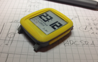 We start with [Max.K] and Chronio. You might think Chronio looks a bit like the Pebble Time, and you’d be right! [Max] based his design heavily on Pebble’s case design. Pebble even has their CAD files on GitHub, which helped [Max] with his modified, 3D printed version. Chronio is Arduino based, using an ATmega328p microcontroller with the Arduino bootloader. The display is Sharp’s 96×96 pixel Memory LCD. A DS3231 keeps the time accurate, and provides a free temperature sensor. The entire watch is powered by a CR2025 battery. Running a 20uA sleep current, [Max] estimates this watch will last about 6 months on a single battery.
![]() Next we have [Joshua Snyder] and Neopixel pocket watch. Who said a watch has to go on your wrist? [Joshua] brings some steampunk style to the party. His watch uses an Adafruit 12 NeoPixel ring to tell time. Red, blue, and green LEDS represent the hour, minute and second hands. The watch is controlled by an ESP8266. The time is set via WiFi. Between the LEDs and the power-hungry ESP8266, this isn’t exactly a low-power design. A 150mAh LiPo battery should keep things running for a few hours though. That’s more than enough time to make a splash at the next hackerspace event.
Next we have [Joshua Snyder] and Neopixel pocket watch. Who said a watch has to go on your wrist? [Joshua] brings some steampunk style to the party. His watch uses an Adafruit 12 NeoPixel ring to tell time. Red, blue, and green LEDS represent the hour, minute and second hands. The watch is controlled by an ESP8266. The time is set via WiFi. Between the LEDs and the power-hungry ESP8266, this isn’t exactly a low-power design. A 150mAh LiPo battery should keep things running for a few hours though. That’s more than enough time to make a splash at the next hackerspace event.
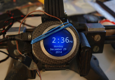 Next up is [ipaq3115] and The Pi Watch. Round smartwatches have created a market for round LCD screens. These screens have started to trickle down into the hacker/maker market. [ipaq3115] got his hands on one, and had to design something cool with it. The Pi Watch isn’t powered by a Raspberry Pi, but a Teensy 3.1. [ipaq3115] included the Freescale/NXP Kinetis processor and MINI54 bootloader chip on his own custom board. He used the Teensy’s analog inputs to create his own 10 element capacitive touch ring. This watch even has a LSM303 magnetometer/accelerometer. All this power comes at a cost though. It takes a 480 mAh LiPo battery to keep The Pi Watch Ticking.
 Finally we have [Vikas V] and ScrolLED watch. Who says a watch has to have an LCD? [Vikas V] wanted a scrolling LED display on his wrist, so he built his own. An Atmel ATmega88V-10AU controls a 16×5 charlieplexed LED array. [Vikas] included a character font with many of the ASCII symbols in flash, so this watch can display messages. Power comes from a CR2032 watch battery in a custom PCB mounted holder. [Vikas] biggest issue so far has been light leaks from LED to LED. He’s considering mounting the array on the bottom of the watch. Shining the LEDs up through holes in the PCB would definitely help with the light leakage.
If you want to see more watch projects, check out our new watch projects list. Notice a project I might have missed? Don’t be shy, just drop me a message on Hackaday.io. That’s it for this week’s Hacklet, As always, see you next week. Same hack time, same hack channel, bringing you the best of Hackaday.io!


Love the pocket watch. I especially love it when things that weren’t made for each other come together like they where made for each other. I don’t think the Neopixel display could be any more perfectly suited for that watch face.
Ugh now I want to make one but I know if I order the parts it will just end up another pile of things on my desk :P
LOL, Me to. We called them ‘Fob’ watches and there from a long long time ago!!
It’s the Dekatron of the 2010’s
Dodecatron? ;)
I’m narrowing the specs down for my watch build now, everything that Woz wants in a watch, everything that Bond ever had in a watch plus ability to emulate any home computer or console up to 6th gen… … and I don’t care if it tracks the number of steps I take, they’ve been doing smart watches WRONG.
Lol; it plays xbox games, breaks glass with ultrasound, and fires lazerz!!
All this for 19 payments of only $19.95!! (+S&H&tax&tire disposal fee…)
I also want to make a pocket watch that does way too much! (Steampunk brass case with laser projector of time and GPS coordinates. Also, really bright LED spot/flood-light.)
This needs a kickstarter!
Won’t the charlieplexed one degrade over time? I seem to recall reading about reverse breakdown of LEDS in charlieplexed circuits killing them?
It really depends on how much reverse voltage the LED is designed for.
I wouldn’t know for sure, but I think the battery will fail long before the display gets too dim to notice.
I can’t imagine that a LED’s Vr < (Voh – Vol) for a micro-controller especially if it's a 3v3 Vcc.
I know it’s a lot more components, but any degradation that could come from having too much reverse voltage across the LEDs could be fixed by putting a silicon diode (1N4148 or 1N4001 through 4007) in series with each one.
There are a bunch of charlieplex array kits out there – I’d be curious to see if there is any significant difference in the LED performance for a kit that spent lots of time on to an unbuilt kit. (not very scientific, but worth a shot)
I keep flirting with the idea of making a GPS clock or watch. The trouble is that it’s just… Too simple. It’s just a GPS module, an AVR and whatever display you want. There’s very little there.
The real trick is adding reliable inertial sensor code so that it doesn’t need to be charged every single day.
Maybe someone will add a 60Hz induction charger so It will charge whenever I’m near the fridge; that would be fantastic. :)
Build one with a supercap and 2.4ghz inverter, so you can charge it in 20 secs in the microwave. :-D
You do realize that I want to make that now…
If this is even imaginable, you may be spending too much time around your refrigerator…
For [Vikas V]’s charlieplexed display: when moving the LEDs to the back side of the PCB, be sure to use plated holes for the LEDs to shine through, or they’ll still leak light all over the place through the glass fibers.
Thanks for the heads up. Hadn’t thought about light leaking through the PCB material.
Actually I will not be able to move them onto the back side because of the CR2032 battery. To fix that issue, I was thinking on using very low profile LEDs like 0.25mm thick so that there is minimal lateral light
perhaps you could ‘pot’ them slightly, but a ring of hot glue around the whole display then use a syringe to squirt in some warm runny potting compound, and fill it just enough so that it almost covers the top of the led but surface tension just stops it. wait for it to set, then remove the hot glue ring.
or i guess you could go over the top of the led and then sand or CAD your way back down..
hmmm sounds a bit fiddly, what about a solder paste stencil? looks nice, two or three stacked on top would be thick enough…
arrrgh, i wish there was an edit button, but = put. CAD = CNC
Thanks for those ideas. Black opaque potting compound can be added between the LEDs using a thin needled syringe. This would work even if the LEDs moved a bit during reflow. I think the problem with stacking solder stencils might be that if the LEDs move a little during reflow, the stencils might not fit. A margin cannot be added in terms of the LED opening in the stencil because that would run into the limits of fabrication (would create very thin segments). Secondly, a polyimide stencil is not opaque and would still leak light. A steel stencil would be conductive!
Thanks again for your insights. I need to experiment to find which is the optimal and low cost method.
Bubble watch .. https://www.tindie.com/products/bobricius/th-retro-wrist-watch-with-bubble-display-qdsp-6064/