In this issue of Hackaday Dictionary, we cover the multiplexer and demultiplexer (also called mux and demux). They are essentially opposites but they work on the same principle. There are three parts: the input, the output, and the selector.
The Basics
With a mux, you have multiple inputs, and a selector chooses which one of those outputs to use, and pipes it to a single output. It’s as if a bunch of people want to say something to you at once, but you can only listen to one at a time.
With the demux, a single input is piped to one (but only one) of many outputs. To continue the example, it’s like you want to say something to a bunch of people individually, but you can only talk to one at a time.
There are also chips that do both; called mux/demux chips. They’re also referred to as bidirectional muxes or switches. These allow the signal to go both ways, so not only can you talk to someone, but they can talk back.
The selector is usually a few separate inputs which are addressed in binary. There is almost always an ‘output enable’ line as well. A 1:4 demux, then, will have the following pins:
- 1 input pin
- 4 output pins
- 2 select pins (because you address the 4 outputs with 00, 01, 10, or 11)
- 1 OE (output enable) pin
- 1 VCC Pin (usually 3.3V or 5V)
- 1 Ground Pin
You’ll often see a ratio in the datasheet, like 1:2, 1:4 (usually a power of 2). This means that a single input can be directed to 2 or 4 outputs respectively. Some muxes can switch multiple signals, so you’ll see something like a dual 1:4, which is the equivalent of two separate muxes combined into a single chip. These are particularly useful when connecting multiple parallel lines (like the RX and TX of a UART) to different outputs.
There are analog and digital multiplexers. Digital ones are essentially logic gates and the output will be at the same voltage as VCC. Analog are more appropriate for reading multiple analog values (if you are short on analog inputs, you can use a single demux to connect a bunch of analog readings to a single input).
Uses
Early uses date back to telephone switchboards. Before the switch existed, there were human operators. Alice would pick up the phone and the operator would answer. That’s the mux part because out of all the phone lines (mostly inactive) the operator chooses to listen to Alice. She would tell the operator she wanted to talk to Bob (whose phone address is Pennsylvania 6-5000). That’s the selector part, where the operator gets the address and selects the jack that corresponds to Bob’s phone. This is the demux part, where one line is mapped to a single out of many possible outputs. Now Alice and Bob can talk. This eventually got automated, and there were giant banks of switches which would mux the outgoing calls and demux them to the appropriate destination. This was necessary because there were only limited wires available between destinations. Here’s a video of how these mechanical switches worked:
One of the greatest uses of a mux or demux is in expanding your input and output options if you are limited on GPIO. If you have a bunch of sensors, you can hook them up to a mux, then have them all pipe into a single ADC pin, and measure them one at a time by cycling through the selector.
A mux/demux is great when you have multiple identical I2C chips, too. Say you’ve got a variety of temperature sensors, but they all use the same address. Rather than have a mess, you can pipe the SDA/SCL lines through a switch, and communicate with them one at a time.
Another neat trick is the ability for some of these chips to do level translation for you, allowing you to mix and match combinations of 1.8V, 3.3V, and 5V components. Some have ESD protection, too, so they are great as an interface to external components where you may not know what’s being plugged in.
These are a handy tool to have. For communications and general usefulness, it’s better to have the bidirectional mux/demux in your parts bins so that you can go both ways as needed, but these are definitely useful parts when you have limited pins either going out or coming in and in a pinch can be used to expand your GPIO-limited microcontrollers.


just guessing this video of the phone exchange is better
https://www.youtube.com/watch?v=MCgCSMq5Xpo#t=15m
Wow! That automatic burglar alarm is incredible!
I’m pretty impressed by the multi-axis nature of these things… Relay-*driven* 3D-printers?
I’d be interested in learning how they train the fish in Cambridge to control the exchange.
The 1:4 ‘mux’ description appears to be actually referencing a 1:4 demux, unless I’ve misread the rest of your explanation (mux: many to one)
You are correct. We’ll fix it.
Happy to help
I think the example may be the wrong way ’round: you’re explanation makes it clear you’d only ever have n:1 mux devices, but the example is for a 1:n device.
Apologies for the repost, and also for the “you’re” – not sure what happened with either! Feel free to delete.
Seems like you are missing one of the most common applications: selecting a memory cell to access, given the address pins.
The way I remember which one is mux and which one is demux is still by thinking of movie theatres (https://en.wikipedia.org/wiki/Multiplex_(movie_theater)): many screens in one place!
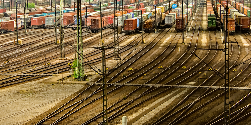
When I first saw the picture I couldn’t figure out why it was used in a mux/demux article. After a moment I realized a railroad switching yard with one rail line splitting into many is a great way to visualize the circuit.
Gonna go out on a limb and guess the author is a serious railfan. Where was this pic taken? I’m guessing Europe since here in the USA we hardly have any cantenary track except for the Northeast corridor and that’s Amtrak/regional passenger service. You pic is serious cantenary spaghetti.
I think it is Hamburg Germany, I couldn’t see the exact image but here is the series:
https://stock.adobe.com/search?filters%5Bcontent_type%3Aphoto%5D=1&filters%5Bcontent_type%3Aillustration%5D=1&filters%5Bcontent_type%3Azip_vector%5D=1&filters%5Bcontent_type%3Avideo%5D=1&filters%5Bcontent_type%3Atemplate%5D=0&filters%5Bcontent_type%3A3d_animation%5D=0&safe_search=1&ca=0&similia_id=60944889&similia_id=39236081
I think you are right, but it’s not exactly Hamburg but the Rangierbahnhof Maschen: https://en.wikipedia.org/wiki/Maschen_Marshalling_Yard
here it is: https://stock.adobe.com/stock-photo/guterbahnhof-in-maschen-hamburg/37470432
Sometimes looking at the filename helps. :-)
I love the article photo! Looks like some kind of electric trolley.