You never know what you’ll find when you open the projects feed on Hackaday.io. Most weeks, The Hacklet follows a theme of some sort. Sometimes I find projects that just look so cool that I have to get the word out about them.
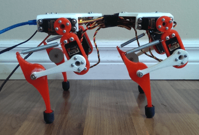 Such is the case with this week’s first project, Mr. Runner created by [Alex Martin]. Mr. Runner is a quadruped robot that really looks the part. In fact, I’d say it looks like it’s ready to jump off the bench top. Like many of us, [Alex] has been inspired by Boston Dynamics, specifically their Wildcat robot. Wildcat had [Alex] searching the net for walking robot designs. He struck up something he liked with the work of [Dr. Fumiya Iida] and [Dr. Rolf Pfiefer]. In the mid 2000’s, the pair worked out of the University of Zurich. Mr. Runner is based upon their work, with plenty of design tweaks from [Alex].
 The basic design is a quadruped with two servos per leg. The servos are at the body and the upper half of the leg. The knee and lower leg are connected by levers and a spring, forming something of a 4 bar linkage. The spring acts as a tendon, absorbing shock, and allowing energy from the servo to be stored and released while the robot runs. [Alex] is experimenting with gaits, controlled by a PC.
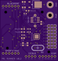
Mr. Runner wouldn’t be doing much running without a way to control those 8 servos. [Alex] started with an Arduino and a LynxMotion serial servo controller. This pairing served him well for the first generation of Mr. Runner. For the new version of the robot, he’s rolling his own board based upon Lynxmotion’s
BotBoarduino. The Gerber files have been sent off to OSH Park, and in about a week, Mr. Runner will be off to the races.
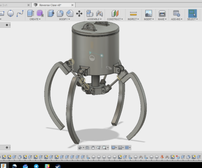 Another great recently updated project is Arcade Claw Game Claw Build by [Alex Anderson]. I spent way too many hours of my youth in arcades, and more than a few quarters went into claw games. Sure, they’re usually rigged, but who hasn’t been pulled in by the chance to test your skill and win a prize? A friend asked [Alex] to design an arcade style claw for a game. A seasoned CNC and 3D printing master, [Alex] grabbed his notebook and started sketching. Rack and pinion designs would work well, but didn’t within the constraints of the game. A leadscrew based design would also work, but would be two expensive. Finally, [Alex] settled on a design and fired up his CAD software. He started with two jaw systems to prove out the basic system. Once that was complete, [Alex] moved to a 4 jaw setup.
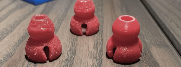
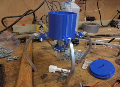 Much like the arcade games, the claw is actuated by a central plunger. The plunger drives linkages which move the 4 claw jaws. Everything looks good on paper, but when the CAD drawings meet the real world, things get complicated quickly. The initial design relied on a 3D printed part which connected the plunger to the jaw linkages. Any slop in this part would be magnified through the rest of the mechanical system. 3D printers aren’t perfect, and there was some slop — enough that the parts would pinch and bind up while moving.
[Alex] already has a revised design in mind. This is very much a work in progress. That’s the beauty of well documented projects on Hackaday.io — you get to see what works, as well as all the trials and tribulations it took to get to a final working project. Keep at it [Alex], you’re almost there!
That’s it for this week’s Hacklet, As always, see you next week. Same hack time, same hack channel, bringing you the best of Hackaday.io!