High up on the list of desirable technologies that are edging into the realm of the affordable for the experimenter is the thermal camera. Once the exclusive preserve of those with huge budgets, over the last few years we’ve seen the emergence of cameras that are more affordable, and most recently a selection of thermal camera modules that are definitely within the experimenter’s range. They may not yet have high resolution, but they are a huge improvement on nothing, and they are starting to appear in projects featured on sites like this one.
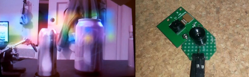
One such device is the Melexis MLX90621, a 16×4 pixel thermal sensor array in a TO39 can with an I2C interface. It’s hardly an impulse purchase in single quantities and nor is it necessarily the cheapest module available, but its price is low enough for [Alpha Charlie] to experiment with interfacing it to a Raspberry Pi for adding a thermal camera overlay to the pictures from its visible light camera.
The wiring for the module is simplicity itself, and he’s created a couple of pieces of software for it that are available on his GitHub repository. mlxd is a driver daemon for the module, and mixview.py is a Python graphical overlay script that places the thermal array output over the camera output. A run-through of the device and its results can be seen in the video below the break.
This may not yet rival the results from commercial thermal cameras, but it is certainly a field in which advances are being made. It is not, therefore unreasonable to expect that in a few years time we will have inexpensive modules with much higher resolution and that this project should be seen as a sign of further good things to come.


Sorry I got got one word for it (rubbish) that’s no good for nothing.
Do what I do and get yourself a real flir gun.
Sorry it’s no good and would not help.
no good for nothing, so you are saying it is good for something then.
English is hard!
Either you’re wrong or you’re smarter than all the people at those companies that are building these thermopile arrays. The usefulness simply depends on the percentage of the instantaneous field of view filled by the object and the temperature difference you’re trying to measure.
Nice website, by the way.
Without experimentation, how would one expect to advance the technology. Early spark gap transmitters paved the way to today’s cell phones.
I am not sure you understand the purpose of this design.
This is a teaching moment.
1) The design shows what you can do at home, previously only possible in a large research facility.
2) It demonstrates a CONCEPT of cheap implementation. Knowing this, seeing it demonstrated enables better applications. For example a larger sensor or a software/servo scanning enhancement.
3) Its cool, in the maker sense of cool.
So as you see, its not “no good for nothing”
Stick around, you will learn more interesting stuff !
Nice, well done. The next step is doing some 2D image tracking on the picam image so the temperature overlay is pinned to the right section of the image as you move it around. That way you can “paint” thermal data on a larger portion of the image.
It doesn’t look like the dynamic range of the sensor array is very large, or is it just the colors you’ve chosen in software?
Another trick for imaging with that sensor would be to remove the lens and place the sensor on stepper controlled gantry under a larger lens and the have it scan a scene.
The thermal resolution could be greatly improved using compressive sensing. It would probably require offloading the processing to something a bit more powerful than the Pi. A general overview of the process is at:
http://dsp.rice.edu/cscamera
what this does is convert multiple samples in time to multiple pixels in space. The GLPK package will do an excellent job of handling the heavy lifting, though there are faster solvers. The hard part would be figuring out a low cost alternative to the mirrors used by the Rice crew. For thermal IR they would need to be gold surfaced. One *might* be able to randomize the IR sensor orientation, but I’ll have to ponder that. There are some complex mathematical constraints that must be satisfied.
BTW I was using compressive sensing methods before I learned about the mathematics. I stumbled across the method by accident and started studying the math when I got better results than I expected. The key is solving Ax=y using least summed absolute error (L1) rather than least squared error (L2) with A being a random matrix with certain properties. It’s easier to do than to understand. I’m still working on understanding what I’ve done.
I like this. It feels more like thermal sensing at that low of a resolution, but overlayed on top of a standard camera image is a great use.
I wonder if anyone has managed to hack the seek thermal range of cameras to work with anything other than the phones/apps they are designed for. I would love to be able to hook that up to a pi running Linux.
Do you think it is possible to work with multiple sensors on a raspberry pi? I’d like to get two to four going. In looking at your example, having more “Coverage” with another sensor or two would give a more full image overlay.
how can i buy it??
These people seem to be selling it (disclosure: I have no idea who they are):
https://www.digikey.com.au/product-detail/en/melexis-technologies-nv/MLX90621ESF-BAB-000-TU/MLX90621ESF-BAB-000-TU-ND/4968086