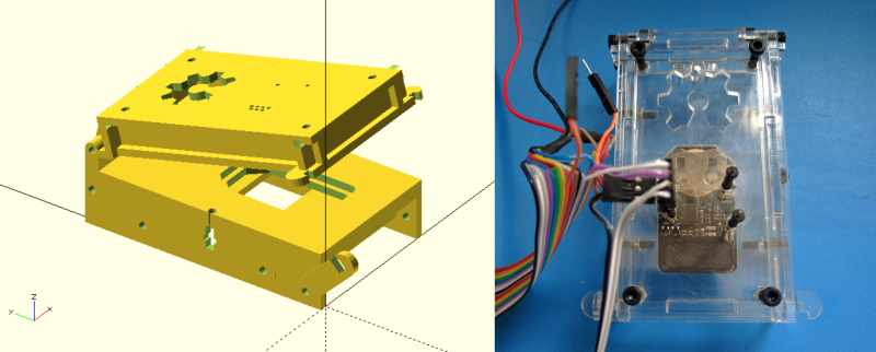
[Elliot] (no relation, but hey, cool name!) wrote in with his OpenFixture model for OpenSCAD. It’s awesome because it takes a small problem, that nonetheless could consume an entire day, and solves it neatly. And that problem is making jigs to test assembled electrical products: a PCB test fixture.
In the PCB design software, you simply note down the locations of the test points and feed these into the OpenSCAD model. ([Elliot] shows you exactly how to do it using KiCAD.) There are a few more parameters of the model that you can tweak to match your particulars, but you should have a DXF outline for a test jig in short order. Cut that out, assemble, and test.
If you have to make more than a few handfuls of a complicated circuit, it becomes worth it to start thinking about testing them systematically. And with this OpenSCAD model, you can have the test jig up and running before the first prototype boards are back in from the fab. How cool is that?


Nice! For a recent project I designed a separate board for programming/testing with the same dimensions as the target. The programmer board mounts the pogo pins and standard headers for connections. I have been looking for a good way to hold the boards together during programming, and this “waffle-maker” design looks like just the thing.
Great idea, this should save people some time!
This is a constrained set of his more general problem, but the boards I’ve made, I put in a through-hole via for each test point, and then use the drillfile to drill holes in a chunk of nylon sheet that the pogo pins press into. (And then cut a board-shaped recess in a nylon standoff on one side, and a sprung latch on the other, so I can pop a board in, snap it into the latch, and run the test program: handling time about two seconds per board.)
Glad you guys like it! There’s been some more development. I’m almost done with a python script which takes a .kicad_pcb file and generates the laser cuttable dxf (current work in up in git repo). The only mandatory inputs now are pcb thickness and material (acrylic) thickness. When the kicad guys finish the python plugin architecture I plan on adding it there so it can all be generated from Pcbnew.
A brilliant tool!! We’ve made one at rLab, but there were a few tweaks needed for our cutter and pogo pins, and some improvements that I can see that might be made…how should we do that? Fork the github repo and make the tweaks on our own copy? For general stuff/suggestions raise issues on your github?
Try Merifix test fixtures, only cost a couple hundred and you send them coordinates and they drill the fixture’s pins for you.
its all a nice little kit that you put together.
http://www.merifix.com