One facet of the diverse pursuit that is amateur radio involves the use of amateur radio satellites. These have a long history stretching back to the years shortly after the first space launches, and have been launched as “piggy-back” craft using spare capacity on government and commercial launches.
Though a diverse range of payloads have been carried by these satellites over the years, the majority of amateur radio satellites have featured transponders working in the VHF and UHF spectrum. Most often their links have used the 2m (144 MHz) and 70cm (430MHz) bands. A few have had downlinks in the 10m (28MHz) band, but this has been as far as they have ventured into the HF spectrum.
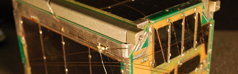
A new cubesat designed and built by trainees at the US Naval Academy promises to change all that, because it will feature an all-HF transponder with a 15m (21MHz) uplink and a 10m downlink. To that end it will carry a full size 10m wire dipole antenna. The 30KHz wide transponder is an inverting design intended to cancel out the effects of Doppler shift. In their write-up they provide a fascinating description of many aspects of cubesat design, one which should be of significant interest beyond the world of amateur radio.
If the subject of amateur radio in space interests you, have a look at our series on the matter, first covering the OSCAR satellites, and then our recent feature on its use in manned missions.
[via Southgate ARC]


The RSP from SDRplay will be perfect for tuning into both the up and the down link simultaneously. Having 10 MHz bandwidth, the SDR can cover both 10m and 15m at the same time. Multi-VFO software like SDRuno and SDR Console will let you visualise everything and compare terrestrial propagation vs the signal from the satellite. There’s a video showing multi Virtual receivers here: https://youtu.be/Wq2K3osyz1M
Jon Hudson – Co-founder and director of SDRplay Ltd.(UK), makers of the RSP SDR – it is good say when you are placing an advertisement.
I thought that the SDRplay had an 8 MHz wide receiving range ? Is it 10 MHz now ?
Butt the real question is how well does it hold up to radiation?
How much radiation do you have at your radio bench?!?
Doesn’t really matter if it’s just going to LEO and probably won’t be there very long. Radiation tolerant electronics are expensive, have very long lead times, and usually very high minimum order quantities that are not practical for little cubesats like this. Common practice is to accept that single event upsets might happen, and have a way to command resets from the ground, or do periodic resets or on a watchdog or something.
I don’t want to nit pick but…..
I used to work RS 12/13 on 28Mhz uplink and around 28Mhz downlink. It must have been 20 years ago.
I believe it’s no longer operational. It’s good to hear of another similar sat going into service.
It might be interesting to see how reception of this satellite is affected by the MUF (Maximum Usable Frequency: the highest frequency at which, in a given moment, a radio signal will be refracted back down to Earth instead of continuing out to space). For instance, at times when 15m signals are being refracted by the ionosphere, will it still be possible to transmit to the satellite? Of potentially less interest because it’s been done before, but on those somewhat more rare occasions when the 10m downlink frequency is below the MUF, will it still be possible to hear the return signal?
Could be interesting to find these things out, if they’re not already known. It’s not a subject I’ve researched.
Note that MUF varies depending on angle of incidence (specifically, 1/cos), and is equal to the critical frequency for vertical transmissions, but about 3x the critical frequency for long-range skywave communications. Thus, rather than considering the MUF or critical frequency as being a sharp cutoff, it’s useful to envision the ionosphere as a reflective dome, with transparent window overhead. When the skywave MUF is below the frequency of interest, the whole dome is clear; when they are equal, there’s a reflective rim just over the horizon allowing skywave communications. When the MUF is above our frequency, but the critical frequency is still below, the window is steadily shrinking, until the critical frequency is reached, at which point the window vanishes.
Anyway, that all applies to communications beyond the ionosphere, and particularly beyond the F layer. As near as I can tell, though, HFSAT will have a perigee of 350km or so, so while it will never be entirely below the F layer, it will sometimes be below the peak density of the F layer.
(Have a live topographical ionosphere map.) Thus the effective critical frequency will be lower when near perigee.
“so while it will never be entirely below the F layer, it will sometimes be below the peak density of the F layer.”
TL;DR It’s a MUF diver :-D
Is the Arduino radiation hardened?
This is a poorly researched article. As a previous poster mentioned, RS12/RS13 already did this.
http://www.om3ktr.sk/druzice/rs1213.html
This is a really neat satellite. Can’t wait to work it.
Yet more good reasons to make circularly polarized HF antennas.
Side Note / Bob Bruninga’s Website design style is legend. I knew instantly I was browsing one of his pages – hard justified images, pastel backgrounds, no fancy ajax or css here. This page will render the exact same on Chrome as it does on a WebTV box from 1997. I say this with love, and as someone who has contributed content to it. Your brain is like “OMG this site is 20 years old!” but he’s sticking with HTML1.0 :)
I’ll be interested to find out what the 10m propagation characteristics are from orbit. I ran a 10m propagation beacon for years, and always marveled about how random my reception reports were…
Nice project, after Brno University HF-PSK mission
… and the old glorious Radio-Sputnik !
An interesting old-new direction to enjoy
Agree with asheets comment, the HF propagation characteristics from orbit is not an ideal for a ground stations. There is more noise comming from the space without possibility to fight with it (need directional antenna with evation rotor, something like https://cq.sk/ako-zdvihat-anteny-v-elevacii-lacny-elevacny-rotator/ ). So this is not a good frequency choice for weak signals. I work through the Amsat Oscar 7 in mode A (145 MHz uplink and 29 MHz downlink) several times but prefer higher bands for a satellite communication. The only benefit of using HF is that the Doppler shift is lower.