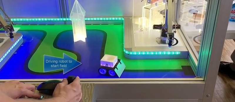
How do you get teenagers interested in science, technology, and engineering? [Erich]’s team at the Lucerne University of Applied Sciences makes them operate three robots to get a gumball. The entire demonstration was whipped together in a few days, and has been field-repaired at least once; a green-wire fix was a little heavy on the solder and would short out to a neighboring trace when mechanical force was applied.
There are some interesting details of the build, including the choice to use an nRF24 2.4 GHz radio for communicating between the main board and the roving robot component, and some gratuitous LED drivers and an interesting time-of-flight distance sensor. Check it out if you’re interested in building small bots.
The game looks fun, and if building cool toys is what it takes to get youngsters into technical education these days, we’re all for it. Whether that’s simple robotic systems like these or a scarily realistic nuclear reactor simulator made of Lego blocks, we have to say that we’re inspired too.


How does the robot charge? Is it very efficiently inductively charged at both stops?
I read through a few pages on how they modified the zumo bot to be two layers and such, but I must have missed the battery write-up. I haven’t looked to see how the zumo charges, if it’s just a battery how long does it last?
I’m also interested in the prototyping problem that mentioned the wrong I2C pull-up resistors, I had thought it was a 1.4K to 4.7K to 10k protocol that you select the resistor based on power and throughput required. With such a large range I would have thought there would be more flexibility.
Thank you for sharing,
We have considered several charging methods, from charging contacts, to using inductive charing up to using super caps. Because of the short timing we took what we have with the existing robot which is charged by 4 AA NiMh batteries. Depending on usage, they last about the whole day so that was an acceptable compromise.
The I2C for the VL6180x Time-of-Flight sensors had originally 10K pull-ups on it: with the added three NXP PCA9685 drivers for the LEDs they were too weak to run the bus with 400 kHz, so we had to make them stronger. Sounds obvious after the fact, but we missed that during the design reiview as things were on separate boards.
Thank you, very interesting!
Pretty cool! Looks like the controls need some work though. Is that a digital or analog joystick? It looks a bit twitchy
Yes, that video shows one of the first sucessful control runs, so things were not as smooth at that time. The joystick is an analog one with the possiblity to rotate the knob as an additional input.
Need a little Godzilla to come up out of the “water” occasionally to present an obstacle for the little car!
The plan is to add an automatic mode in which the machine is trying to do things faster than the human operator. For this the robot will follow the black line as fast and as best as possible.