[B Arnold] is hearing voices and needs help from the Hackaday community. But before any of you armchair psychiatrists run off to WebMD, rest assured that [B Arnold] suffers not from schizophrenia but rather has an RF coupling problem.
The project (which isn’t posted yet) is an attempt to turn a C.H.I.P into an Amazon Echo, for which [B Arnold] needed an audio amplifier. Turning to the junk bin, he unearthed an LM386, that venerable power amp chip that first appeared in the mid-70s. Dead simple and able to run off a 9-volt battery, the LM386 that has found its way into thousands of commercial products and countless hacks.
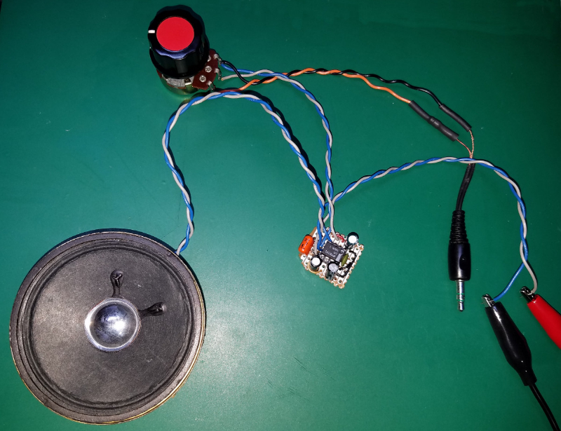
Shortly after applying power to the amp, [B Arnold] started hearing things – faint, far-off voices, scratchy but discernible. A bit of repositioning of wires and hands improved the signal enough for a station ID – an FM talk radio station on 97.1 MHz. [B Arnold] doesn’t mention the call sign, but it might have been KFTK out of St. Louis, Missouri; in any case, it would be helpful to know the range from the transmitter to the inadvertent receiver. Two low-fidelity audio clips are included below for your listening pleasure – you’ll want your headphones on, and Sample 2 is better than Sample 1 – as are photos of the offending circuit.
What do you think is going on here? We’ve heard of RF coupling of AM radio stations before, but how would FM signals be making it into this circuit and out of the speaker? Is there anything [B Arnold] did wrong to get this result? Sound off in the comments and let us know your horror stories of RF coupling.
Sample 1:
Sample2:


 Fail of the Week is a Hackaday column which celebrates failure as a learning tool. Help keep the fun rolling by writing about your own failures and sending us a link to the story — or sending in links to fail write ups you find in your Internet travels.


KFTK simulcasts on 1490 AM. Likely picking up that signal rather than the FM equivalent.
That makes sense. Surprising though since I tracked down the station by flipping through channels on my stereo and never found a match on the AM side. That’s the only reason I flipped to FM and continued my search.
Instead of guesswork, build a little FM bug, tune it to that frequency, place it ten feet from your amplifier and try to hear it. If you don’t hear it, you are probably not receiving FM. Don’t modulate too much, or the FM bug will produce AM, too.
Another test would be to make a simplest diode detector (without tank circuit) and see if you are receiving the same station.
Or around 40mhz stations are often broadcasted here for “”HD”” equivalents
What are the odds the station is simulcast on both AM and FM, considering it’s talk radio?
There is a talk station here in Portland that simulcasts on FM and AM so it is possible.
Second audio clip sounds like George Norry’s show. Coast to Coast.
Which was art bell’s show who spawned the lizard people conspiracy guy, alex jones. waaaayyy back in the day when I had a third shif tjob, I’d listen and chuckle at these nut jobs and their tin foil hats. Today, its not near as funny….
I’ve had this happen with a simple TDA2822M amplifier circuit I built on a breadboard. It was picking up multiple stations simultaneously including a music station, so I’m pretty sure it was FM. There’s a number of FM stations which broadcast off a mountain 25km away so the received signal strength was probably fairly high. I’ve always wondered what was happening.
I have done this for a short period with a Prusa I3 3d printer. you could probably find my post about it somewhere on the internet.
I have done this as well, except with a Prusa i2 :) link https://youtu.be/W2r8HCY6Ers I have also managed to do this with an LM385 I was making an small audio amp as well listened t ok AM stations on it for a while :)
One day a broadcast engineer I know got a call from a local resident by the radio station he worked for. Complaint was his stereo played station…. Even when it was UNPLUGGED! Investigating engineer found speaker wires acted as antenna. Output transistors were acting as detection diodes, turning RF into LF audio which then drove speakers just enough to be heard. Friend just added a few RF decoupling caps to cure problem.
Several years ago I found placing my PC’s subwoofer too close to my metal desk caused it to pick up a radio station. That was a confusing day.
Back in the 60s and early 70s, I had a friend who lived in a suburb of San Diego, and just so happened to live directly adjacent to the 6-tower antenna array of a 50KW AM station on 1.170Mhz. He could hear the station on just about every electronic device in his house. We went thru what we could with ferrite beads, but even that was not enough.. He moved a while later. I can just imagine everybody else on that street that had this station in their backyard. I see now that station has changed formats and moved their transmitter/towers to a more remote location.
If it were bit later when fluorescent tubes existed he would have had free lighting lol.
I used to work in a 15kW government run AM station and a lot can be said about government stupidity because of that issue. We used to carry around fluorescent tubes for light and never put them in the light fittings because of a completely stupid unbend-able *policy*.
The policy was that all spare parts to keep the station running *must* be kept onsite. We even had diesel backup generators.
Problem was that the flureos would be running all the time from when they arrived so they would only last a short time in use so they bought more of them to compensate. In the end we had a large store room built just for flureos. There were approximately 10,000 tubes in that room even though the entire building only had about 200 light fittings.
We all took turns to fill out an ‘indecent report’ to explain how we ‘fell over’ in that store room and accidentally broke all 10,000 tubes. In reality a fork lift was involved in the smashing of the tubes but we wanted to sent a message to the bureaucrats at the other end about how stupid the policy was. Once they were all broken, we got a fresh batch of another 10,000 and they would last a while.
“You’re not wrong, Walter…”
It’s more like “Waldo”.
Perhaps I should have mentioned that tubes last around the same amount of running time. You get to a point of needing another tube and there are 10 left in the 10,000 that still work and even if you were willing to spend 2 hours finding a working one then it would probably burn out before you get it to your work location just as has happened to the other 9,990.
So while the indecent report wording was very pointed, smashing the remaining 99.9% faulty tubes was the only practical solution.
@RÖB: 10000 tubes can not be run on full power from a 15KW transmitter. I can not imagine a store room of 10000 glowing tubes. why wasn’t it shielded to some extent?
Smashing 10000 tubes releases quite some mercury, around 100gram, if each tube only has 10mg of it. Lighting 10000 tubes from the RF would draw quite some power off the transmitter.
They don’t *run* let alone at full power in the store room. A tube normally has a voltage difference from one end to the other and that is not exactly what happens in the store room. In the store room they are effected by RF energy than makes them glow and is different to how they normally work.
In the work areas closer to the output stage (which was a large room with a deadmans trip on the only door) they worked very brightly. If you wrapped your hand around a part of the tube it would be brighter there. Wrapping some aluminum foil over one end helped to.
As mentioned – there were only 100 or less fittings to 10000 tubes is 100 tubes per fitting so if a tube lasts 3 years then that’s 300 years supply or in simpler terms – for every year they would be expected to be in a fitting they would have to last 99 years in the store room so obviously, even at lower powers than their rated capacity they are never going to last long enough to out last the expected time in the fitting but that never happens because they don’t last long in a fitting because of how long they spend in storage and working at lower powers. Can you see the catch 22 here?
And mercury, these were older tubes that had higher levels of mercury. I have often been called ‘mad as a hatter’ so perhaps that history has something to do with it. I always thought that it was because I use lead based solder to pick my teeth. But anyway, it’s all good, I have a diagnosis now :)
The decoupling capacitor (RF shunt) is at the opposed end of the longest traces on the board to the power wires and this is forming a nice little folded dipole antenna.
I think it is much more likely he is simply picking up AM on those *unshielded* input wires connected to the pot there. LM386 set to high gain makes a lovely direct amplification receiver (or oscillator, if you aren’t careful).
If he switches to a shielded wire for all input connections and puts a low pass filter at the input close to the chip the problem will be gone.
Without a schematic or figuring it out from the circuit, I can imagine FM being turned into AM by being centered right on the edge of a filter’s passband, or maybe just by being anywhere on a steep enough slope. Maybe this gets enhanced by being mixed in some diode by some other signal which creates another signal at an intermediate frequency. What does a distorted FM signal that’s been distorted by an ESD protection diode circuit look like?
I can also imagine something odd in the transmit circuitry that could maybe cause the signal to be slightly AM modulated in addition to the intended FM.
This is the schematic I followed.
That is weird. I can see the link in this page’s source.
Lets see if this works:
https://s11.postimg.org/8z966x1ar/LM386_Amp.jpg
Hello,
Use a shielded cable for your input! That’s where your sensitive amp is picking up the local radio station. If that doesn’t solve it already, put lowpass filter at the input to block the RF.
If you look in the datahseet, you can see an AM radio amplifier in the typical application section here:
http://www.ee.ic.ac.uk/pcheung/teaching/DE1_EE/Labs/LM386.pdf
It includes an input filter with a 10k resistor and 2200pf capacitor. For the output it uses a ferrite bead and instructions for tightly twisting the wires, as you’ve already done, but maybe tighter than that. The shielding of the input as has been mentioned should go down to the PCB. The PCB should be enclosed in a metal box with the ground connected to the box, or shielded using aluminium or copper foil.
You don’t have to use it as an AM radio amp of course, but it will have protection against HF, that’s the main thing you can copy for your own applications.
All components must be spaced as close as possible, including the input jack, potmeter and speaker.
But this AppNote suggests using it as an audio amplifier AFTER the detector – not as the detector itself :-) One time I received my brothers 27MHz FM CB radio in my stereo. The antenna, radiating 4W of power, was just 3m away and obviously there was some FM to AM conversion, either in the transmitter or in my unintentional receiver.
27MHz CB was AM/SSB
@RÖB:
In Austria (Europe) in this time (1990 something) it was sure FM and 40 channels. Perhaps there was some residual AM, as the switch on click of the transmitter was louder than the voice.
There’s a reason that C3 is shown directly to the IC pins 6 and 4. Delta pin 3 – 2 is in reference to the absolute value of 6 above 4 but the gain of delta pin 3 – pin 2 is R1 / (Xc C1 + (1 / 2Pi (c5 / R2)))
I got that wrong by the way I added the frequency compensation of C1 to the shunt of R2 / C5. Bu this bring hackaday … someone will – no doubt – correct me!
Looking at schematic the thing that jumps out at me is the cap on pin 7. Data sheet suggests 0.1 uF or even SHORT to ground IF you use higher gains (cap between 1 – 8).
I think you used ‘ when you should have used ” in your a href tag, that’s all. :)
I came here to say pretty much this. It’s called “slope detection”; the FM signal on the slope of a filter’s response becomes Amplitude Modulated by the filter. Parasitic circuit elements, (adjacent conductor capacitance, along with inductance contributed by wires, electrolytic capacitors, possibly a power supply transformer, etc.), could create such a filter, and semiconductor junctions in the IC would act as diode detectors. The filter would likely have a low Q factor, meaning it would have shallow slopes and would be ‘lossy’. This could account for the low amplitude of the signal. If this is indeed the case, changing the physical layout of the circuit will almost certainly change the behaviour. If you simply want to get rid of the problem, try inserting ferrite beads into signal and power connections. Ferrite beads aren’t just inductors; although they DO have inductance, they are designed to work as ‘RF resistors’ and actually dissipate RF energy in the frequency range for which they are designed.
Of course, as others have commented, it may simply be that the content is being broadcast on both AM and FM. Even if it’s an AM source, ferrite beads will help to suppress it; small capacitors, (in the range of, say, 100pF and 1nF), between these lines and ground, may also make a difference. (Depending on other factors, the difference may not be a positive one…) Another thing to take care of is proper grounding. A single long bus wire IS ground for low-current DC-through-audio frequencies. But at higher currents its resistance starts to matter, and at higher frequencies its inductance starts to matter – in these cases some point on your ‘ground’ aren’t REALLY grounded. Ground planes are (usually) your friend in these cases.
^THIS^ I was gonna say it, but got beat to the punch… Decouple any input wires! I have had this problem myself, and it CAN be caused by FM because of this, not just AM. Slope detection is commonly used as a simple, low cost way to decode FM, especially if you don’t need a lot of fidelity, as in low bit rate digital data streams etc.Small decoupling capacitors, ferrite beads, and careful circuit layout are going to be your friends, like was mentioned above. You may have to put the amplifier in a small metal or fr4 box even. An LM386 has a lot of gain when you put the cap across pins 1 and 8!
Yep: Encapsulate the box and surround it by low pass filters. An inductivity in series with the input might be sufficient.
For try-and-error-makers the strategy ist different:
“Tune in” to that station and grab some potential countermeasures like aluminium foil, cookie jar, pringles box, wet finger between input and ground etc.
That would also explain the signal distortion. It pretty much sounds like nonlinear distortions as caused by a rectifier / diode. Younger folks might associate a “bitcrushing” effect, anyway, the signal appears wave clipped to me.
I remember having AM signals in my guitar amp when we still had strong AM stations. That sounded totally different.
We have an AM radio station playing when our computer is switched off in one of our theatres. All very expensive high end gear, just must have the wrong length cable somewhere. It’s the most bizarre thing to hear.
Expensive and excellent are two different things.
Anyway, all these things “strange” and funny experiences people have/had are the main reason why we have FCC and CE regulations.
Now the schematic, I’m sure it really helps to keep the wires short, the potentiometer should/could be shortened a lot. this reduces to antenna function of the input leads. So in short keep the 10K as close to the amp as possible, then it might help to put a small capacitor across the input to ground, shortening the possible RF signals. Also using a smal ceramic capacitor 10nF (electrolytic doesn’t do anything block with HF) across the power supply may help a lot. Amplifiers being radio receivers is nothing new and I’m sure that many people build the same setup without problems, claiming that they never have heard a radio signal on their 386 long wire badly decoupled amplifier. Well it all comes down to luck, if there isn’t a radio signal strong enough on the location you are using it or if you are using slightly different caps, wiring layout etc. blabla. So in short, decoupling, filtering and short wires, do this for every design and you are most likely have less problems.
Regarding FM detection on a simple system capable of AM only is nothing new, it is called slope detection and mentioned in one of the other replies.
http://www.radio-electronics.com/info/rf-technology-design/fm-reception/fm-slope-detector-discriminator.php
It is a very interesting technique. The only real reason it why we don’t receive FM signals on our normal (consumer) radiosets is because the tuner does not allow user to tune in to the FM range. If it was possible then it would be more well known to the major public. There is of course a drawback, slope detection is much more fiddly then a proper FM detection circuit and that means that quality will suffer but in this case it will only add to the mysterious noises coming from the speaker, the gently noise hissing through the speech, the reduced bandwith combined with other artefacts of the circuit itself being tuned by hand-effects and internal oscillations… whoo hwooo mystical.
Nope, just electronics, decouple, shorter wires, perhaps additional filtering of the psu.
Hang on, be patient, work carefully and think about the possible HF paths you’re creating and if nothing helps… well perhaps electronics are simply not your thing (at this moment you might be just at the beginning of the learning curve, in that case hang on, this is completely normal do not worry, just hang on) and you might consider to simply buy the cheapest amplifier you can find on the internet and nobody has to know you failed to build this deceptively simple design.
Lot’s of people forget that electronics is more then slamming parts together and expecting it works straight away. I’m always amazed that in this time of arduinos some people expect to have perfect results by connecting a voltage devider with one thermistor and expect that the arduino will do something magical. Just because it has a many-bit ADC. Well sorry, there is always noise, there is always self heating, there is always drift, there is always power supply inaccuracy or dependency. If you are not aware of this your project WILL fail, especially if you expect to get 0.1 degree Celcius of accuracy from a single measurement. Resolution and accuracy are two different things. Hackaday should do a item about that but now I’m getting of topic.
Resolution and accuracy, or lack of it. See http://www.surfacestations.org
In Poland whenever You attempt to make a simple radio You hear Radio Moskva :)
Normal thing in this play.
Radio Moskva hears YOU!
When I was a kid, I ran about 5 meters long wire outside. Just two wires, not shielded, connected to a tiny microphone found inside a cassette player, the other end connected to a computer. During sunlight I could hear birds signing, at night I heard like dozen AM radio stations at once.
Weirdest thing I’ve heard stories about picking up a radio station is an old kitchen sink. The best explanation was that somekind of crystals formed under it over a long period of time. Didn’t see or hear it myself though… well, this IS Hack-a-day so maybe somebody could give it a go? ;)
Copper sulfide semidonductor?
“Weirdest thing I’ve heard stories about picking up a radio station is”
Lucille Ball’s interesting story claiming that her fillings were picking up Morse code from an ‘underground Japanese radio station’/spies.
Also … twisted pair wire in cables has the twist reversed in sections to cancel the inductive properties of the twisted wire causing signals from *other pairs* interfering. In any other case twisting wire is just adding an inductor unless you are using a *balanced* signal and in this later case it rejects external interference *only*.
PS: *balanced signal* is old speak for *differential signaling*.
“an FM talk radio station on 97.1 MHz. [B Arnold] doesn’t mention the call sign, but it might have been KFTK out of St. Louis, Missouri; in any case, it would be helpful to know the range from the transmitter to the inadvertent receiver.”
I’m located in the Saint Charles, MO area around Highway 70. Unless the info I found is bad or there is a repeater nearby, the two stations aren’t particularly close. That said, I can’t say I know exactly what close is when it comes to a commercial radio station.
1490 AM East Saint Louis, IL
97.1 FM Florissant, MO
This is exactly why they taught us to use the shortest wires possible in practical training for my physics bachelor. There are just too many RF signals around. Anything that can be an antenna will pick up signals.
Use the shortest possible wires and lay them flat.
I’m surprised that nobody mentioned the obvious problem with this circuit. A red wire is being used as a ground and a black wire as voltage supply. The electrons (at least those that aren’t colorblind) are definitely confused.
With the wire-color polarities reversed like this, I’m surprised he’s not receiving signals from the world beyond!
Joking aside, it really is a bad idea to deviate from standards (informal or not).
Standards I have to adhere to state that (+) potential is red, (-) potential is black, (ground) is green.
When I wire up most UMTS or LTE equipment in the cell sites, if they are +24VDC, their (-) black goes to ground; -48VDC has (+) red to ground. All grounds go to a common buss bar which exits the site to Earth with a green wire.
This is mostly correct. Green is always a reference (and ground for obvious reasons), Red is always above the reference, and black *should be* below the reference. When you connect a battery negative to the reference or ground, you should be using a *blue* wire instead of black.
It’s the same for other things to, for example: 9 Volt battery connectors are often referred to as +9 Volts and -9 Volts but they don’t have a difference in potential of 18 Volts so they should be called 0 Volts and 9 Volts.
Agree with the blue wire thing- some of the earlier equipment used that.
However with the newer stuff, we weren’t allowed to use any colors on power and ground leads other than red, black and green for most wires though occasionally we had to use gray because of other ‘local’ carrier requirements. Wasn’t much of a big deal to most of us since we also labeled the conductors’ functions near the connection point with either ‘fiber paper’ tags secured by string or with label maker printouts under clear heat shrink tubing and on gray cable, applied colored tape or heat shrink.
Another example besides these cell sites is vehicles with positive ground electrical systems which typically have a red lead from the battery to the frame / chassis. This is one reason they tell people to not let the vehicles touch when jump starting.
For me normally black is the reference/GND in electronics and a negative voltage normally is blue. Green I normally don’t use, but I saw it sometimes in building installation for light switches for the switched line. But that can be “anything”, also orange or violet, etc. except yellow/green which is reserved for earth GND (PE).
@KDM:
I think the most obvious reason to not let vehicles touch is that it can damage sheet metal and the paint. But even with two GND negative vehicles it is better to force the electrons through the cable in a controlled way.
I see lots of people allowing their cars to touch other cars in car parks. I call it the ‘acoustic’ parking method.
These new cars that have a row of yellow LEDs for indicator lights are a departure from standards.
10% of the population is color blind and older indicators were made so that color blind people could *also* see them.
Now these new cars have indicators that 10% of the population can’t see. There a death trap on wheels because of a problem that normal vision people will never be aware of.
Depends on what country your in – some indicators are white ours in Australia are orange ….
Well that may be the case for a normal vision person but to a color blind person the color is irrelevant. I am in oz to.
Color blindness is one reason that the position of indicators on the vehicles is regulated, and the same reason why traffic signals lamp positions are defined and traffic signs have their various shapes detectable at a distance.
The position of the indicator lights that I mentioned is high up and as a part of the headlight enclosure and that is a good part of the problem.
Because of the curve of the headlight enclosure, direct sunlight is entering and reflecting from the indicator section. If you can see color then this is no problem as the color changes when the indicator flashes but if you don’t see color then you have to rely on contrast and there is very little contrast change due to the reflected sunlight, so little in fact that I can’t then except when it’s dark or night.
Being over here in California, I don’t think it’s appropriate to make fun of the colorblind, nor to assign function labels based solely on color. Imposing strictly defined functionality may result in issues such as feelings of inadequacy or lack of confidence, or may be discriminatory. Perhaps they are functionally challenged, functionally confused, trans-functional, or in functional transition.
Anyhow, either (+) or (-) can be grounded, depending on various things, so without testing with a meter, I wouldn’t have mentioned it because without a declaration from the maker, I don’t know if the power source uses a positive or negative ground… or even know if it’s grounded at all.
94.9, here… on dang-near every amplifier I’ve made like this one. Took many tries and years of study to realize op-amp circuits just ain’t my forte. Glad to see some folk aren’t utterly-shocked at the FM-reception, and some potential explanations for it!
Why did I not know this some decades age, when I was in school and built a small FM radio. I could have saved the expensive TDA7000, if I knew that the LM386 I used could receive FM broadcast by itself. :-)
Clean up between tracks on the back of the board again, you get some freaky detector diode effects from tiny little tin whiskers off the solder sometimes.
I live close to a transmitter tower and have an attic full of mostly “vintage” analog synthesizers. They are always picking up stray radio signals. Fortunately, my HAM operating neighbour has moved.
Ground issues?…
HH scott MA100 100W guitar/instrument amplifier (60W RMS) amp board and transistors are the only thing I kept.
The thing is designed to take abuse and operates down to 3Hz (on batteries the last time I watched a sub move back and forth with the amp.)
Some sockets in my flat have earthing issues. Metal surfaced appliances (grounded) on some sockets have that “rubbery” 120Hz feel to them and are fine in most others. The rented accommodation association won’t bother fixing: LOL (:S).
Had the MA100 amp module via the power in route the ground leads into one of the badly-wired-earth sockets (Via the earth pin of course and that strangely passes those cheap hardware store socket tester).
The amplifier would pick up a few radio stations with the lead loosely coiled on the floor.
On batteries (Surplus E-POS Ni-MH Split rail config) it’ll work fine.
I’d sacrifice audio quality for filtration by using ceramics for the input (between line and GND), placing a 1K resistor in series with the amp pin after a (minimum 10uF) capacitor and placing a zobel network on the output to ground some of the HF from causing possible feedback (oscillation/resonance prevention).
A bit overkill, especially for a “low component count” design. However should improve things.
Where I live, that rubbery 120Hz feeling is potentially fatal. I would get checked.
I’m reasonably certain that’s a bad sign regardless of your locale. It makes me wonder what kind of third-world shithole he lives in – then I realized it must be Britain, where they consider antisocial behavior more of a threat to life and property than malfunctioning mains power.
I once received radio signals when I was playing with a cup of water a power supply and a radio shack learning lab board.I cut off the end of the barrel jack and put one side in the water, one side through the 1 ma power meter, and a jumper between the water and the meter. I could hear a faint far way sounding radio signal just like the samples provided. I added salt to the water and the signal went way.
1. My homemade microphone amplifier did the same. The problem disappeared when I realized, quite a bit later, that modern transistors easily have 300 Mhz frequency limit. By amplifying audio frequencies, you can easily amplify FM or AM, ***IF*** your amp is not bandwidth limited. Solution? Placed 100 pF – 1000 pF capacitors from transistor bases and/or collectors to ground. Then you are limited to few 10s of kHz and all is good.
2. My diy 27 MHz receiver would receive strong AM/FM stations when outside. Solution? A) placed the whole thing into the steel box. Much better, since AM could no longer get to any radio component inside willy-nilly, just to antenna terminals. But still I could hear some AM. B) placed high-pass LC filter at the antenna terminals. Problem finally fully solved.
Since those experiences, I started bandwidth limiting all my amps. Audio amp does not have to amplify FM, and by golly radio frequency amp does not need to amplify audio :)
Guess I’m too old. We were doing this on purpose back in the late 70s and early 80s to make radios from junk parts. Before I knew how to deal with FM, I was building AM radios from lm386 and other opamps and building in tuner sections to go up in the FM range.
It could be being received from Chicago. (97.1 the drive.) The thing I have found with my SDR is that FM stations can be AM demodulated to get a bad sounding version of the station. I might make a hackday.iopage about the exploration of FM stations over AM.
On the topic of accidental and radio. Was tuning the Z-axis stepper on my Morgan 3D printer and stumbled across a combination where a radio station could be heard from the stepper. I guess what was happening is that the resonance of the motor or stepstick (because it was not holding fast, probably between steps) somehow ran at the beat frequency of a radio station and mixed it into the physical motion of the stepper which in turn generated audio. If I dampened the resonating axis with my fingers, the music would stop :) There’s an idea for an odd speaker. No bass thought :)
B Arnold isn’t the first to unintentionally make a radio with an LM386 audio amplifier. I had the same problem with the same chip. But it was at least a couple decades ago, and I don’t remember if it was picking up AM or FM. And I don’t know if or what I did to fix it. So I guess I have nothing useful to add. I’ll go now….
Slope detection as others have mentioned would be quiet possible.
I many many yars ago made a mixing console and been short of cash needed a small signal Audio amplifier and had a pocket transitor radio lying around so I just disconnected the connection between the detector and the audio amp and used the audio amp stage – unftrunately if the radio happened to be tuned to a suitably strong radio station it would still be heardthrough the system :o
I believe thiw was covered by hackaday already but here is an interesting link
http://theradioboard.com/rb/viewtopic.php?f=4&t=6413
I beleive ths was covered on hackaday before but here is the link again anyway
http://theradioboard.com/rb/viewtopic.php?f=4&t=6413
My BMW radio still broadcast the previously selected fm radio when I switch to aux. I can hear when there is nothing plugged on aux. Q