
At this point, the internet is crawling with butt-kicking homebrew 3D printers made with extruded profiles, but it’s easy to underestimate the difficulty in getting there. Sure, most vendors sell a suite of interlocking connectors, but how well do these structural framing systems actually fare when put to the task of handling a build with sub-millimeter tolerances?
I’ve been playing around with these parts for about two years. What I’ve found is that, yes, precise and accurate results are possible. Nevertheless, those results came to me after I failed and–dry, rinse, repeat–failed again! Only after I understood the limits of both the materials and assembly processes was I able to deliver square, dimensionally accurate gantries that could carry a laser beam around a half-square-meter workbed. That said, I wrote a quick guide to taming these beasts. Who are they? What flavors do they come in? How do we achieve those precision results? Dear reader, read on.
But First a Brief History Lesson
From college optics labs to factory floors, it’s too easy to let these extrusions fall into the cast of minor characters that were simply “always there.” After years of taking them for granted, I started to wonder: where did they come from?
Our story starts back in 1797, where [Joseph Bramah] coined the concept of squeezing a pre-heated hunk of metal through a precisely-shaped die. Behold — the first extrusion was born! Today, just like in the past, extruded profiles are made from a grown-up version of the process. (Nice job there, [Joe!] Your concept managed to stick around for the last two hundred years.) From here, though, the origin of our beloved X-shaped profile gets a lot murkier.
Digging through patent after patent from the last five decades until now, I still can’t find a clear single inventor of the most common structural framing systems that we see nowadays. (Fellow engineering historians, HALP!) Instead, what I’ve discovered is a slow, maturing system of interlocks evolving for years without standard until they finally morphed into the modern systems like Rexroth and 80/20.
Reading the patents, it’s actually rather exciting to see common tricks both reinvented and improved over the years. Starting in the mid 60s, we start to see basic extrusion elements that interlock at the corners. Their cross-sections are rather complicated, but the fundamental concept of interlocking elements is present. In the late 60s, we start to see slotted inserts and derivatives. In the 80s, we see mature ‘T-slots,’ albeit in an unfamiliar profile. In the 90s, we have something that’s far more mature: a simple, repeatable slot pattern reproduced on various geometric shapes.


Should we be surprised that no sole human can call “structural framing systems” their personal claim to fame? Nah. Competitors riff off of each other time and time again. Thomas Edison’s lightbulb was inspired by a previous inventor, Joseph Swan, who goes on the record for being the first person to put a filament inside a vacuum to prevent it from burning out so quickly. Alexander Graham Bell, the most memorable of the telephone’s many inventors, based much of his research on both experiments conducted by Hermann von Helmholtz and, with some debate,patents already filed by Elisha Gray. Like many inventions, even those credited to a single person, structural framing systems are most-likely the creative effort of many curious people over many decades. On that note, we can thank our predecessors for refining a once-crude system into the tested-and-tried elements that we know today.
The Competitive Budget Alternatives
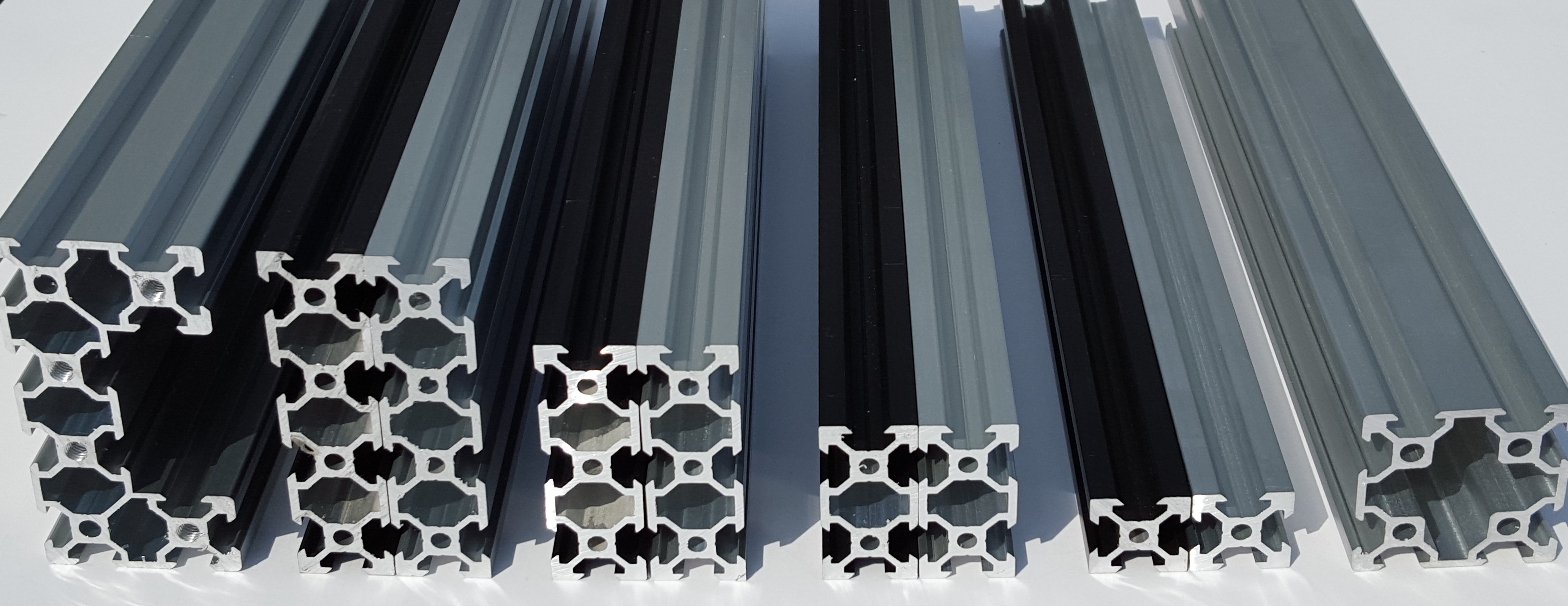 Extruded profiles used to be pricey, but these days a few Kickstarter campaigns have knocked down the price with a few cheaper lines, namely OpenBeam, MakerBeam and VSlot. Each of these extrusions is more than capable of handling the day-to-day extrusion needs of the hobbyist. Let’s not get too smug, though. Admittedly, when I first discovered these cheaper alternatives, I remember thinking: “Those poor industry design engineers — all of them enslaved by corporate partnerships to pay truckloads to some overpriced big-name profiles; meanwhile I can pay half price on something that works just as well!” Truth be told, these maker-breeds are fundamentally different, so it’s best to understand what we’re paying for when we pick a budget alternative.

So what sets those shiny, industry-standard profiles apart from these budget alternatives? First off, most of our friendly commercial leaders have been in the business for well over a decade, so it’s pretty safe to assume they’ve been chewing on their nails long enough to get a few things right. As a result, they’ve ironed out dozens of use-cases for extrusions and their various interconnects, everything from clean-room grade profiles to “here, hold my coffee.” Rexroth alone has over a hundred various extrusion types and a host of brackets and connectors for just about every possible hooza-ma-whacha-doodle we could possibly throw down on a factory floor. What we get from inventory is convenience.
Second, these companies have had both the time and resources to characterize their material library. What this means is that we can quickly find material characteristics of these profile, such as their section moduli and moments of inertia, to help us better estimate the limits of our materials before committing to them. (GIANT PDF Warning: Rexroth Structural Framing Elements Catalog) Finally, most heavy-duty industry players make their extrusions from 6061-T6, aka: good-ol’ aircraft grade Aluminum. Each of hacker-friendly maker alternatives is formed with 6063-grade aluminum. As for the differences, 6061 has about twice the yield strength and hardness over 6063. Should these structural differences matter to you? For small gantry builds, probably not. On the other hand, 6063 is noticeably softer than its 6061 cousin, so keep those corners safe! Just to emphasize the soft part, here’s the effect of a recent unintentional ‘impact test’ that happened during transit around my garage.
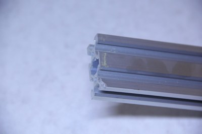
Again, nothing too serious here, but if that same dent landed on one of the internal channels where roller wheels would slide, the entire profile would be hosed, at least, for the purpose of guiding around a rolling carriage.
Even though most small builds will never need to consider some of the benefits earned by the industry leaders, it’s to our benefit to know what the implications are when we trade pricetags for a budget alternative.
Designing in a Real World
For the untrained soul, CAD might sound like engineering wizardry, but the actual process of modeling parts is actually pretty straightforward. Sure, every software package has its kinks (**cough** Eagle), but, like any capable user, we can learn to work around them to get the result we want. As for getting the real-life model to precisely match the dimensions of the CAD model? Now that’s a bit trickier. In this next section, lets take a look at some of the principles behind these parts and how to work with them in a way that preserves the dimensions that we first put into the CAD model.
Structural Framing Systems Aren’t LEGOs®
Structrual framing systems arrive with a host of classy brackets and interconnects to help us build up large structures quickly. However, while parts might seem to snap into place, the reality is that they’re a bit sloppier, so nailing down the dimensions that matter takes a bit more effort.
In a perfect world, these extruded profiles and brackets would behave like the LEGO bricks of our hey-day. In that world, profiles and brackets would only fit together in a limited range of configurations–each of which guarantees some sort of constrained relationship between those parts. Put better, as MIT Media Labs’ founder [Prof Gershenfeld] would say, “the metrology comes from the parts“. [Gershenfeld’s] best example of this concept is with LEGO bricks. Since each brick is properly dimensioned and only accepts certain configurations by which other bricks can connect to it, we can predict the sizes our our Lego configurations just by keeping track of all parts we used and how each part connects to the other. (Of course, this concept assumes that bricks are manufactured “ideally,” which , for all intents and purposes of the folks out there playing with LEGO, we’ll assume is true.) In that world, we wouldn’t need to measure anything, or, as [Gershenfeld] would say, “you don’t need a ruler to play LEGO.” Why? Because simply by inherent nature of the part metrology, assembling parts together would preserve an ideal geometric relationship between them. As a result we’d get two benefits: first, our components would fit together only in a limited number of configurations; second, once we assembled our components, their dimensions would directly reflect the CAD model.
Well snap, we don’t actually live in that world, so each one of our brackets and fittings has some form of slop. In each of these cases, we need to understand where this slop comes from and how to handle it.
Understanding “The Wiggles”
Lets get started by looking at the slop in common interconnect techniques.
Heads up: I’m using VSlot components for these examples since the OpenBuilds folks have been kind enough to provide the community with their CAD models. If you’re not using OpenBuilds components, don’t fret. Most structural framing systems come with a choir of brackets and interconnects that look just like the ones in these examples.
Coplanar Slop
Corner brackets are one of the easiest ways to join two profiles at 90-degrees, but they’re notorious for their slop. On the left is a depiction of just how much of a range of motion we have before we fasten down those screws. Where does this range of motion come from? In this case, we’re assuming ideal components, so the slop comes from the four gaps between each T-Nut connector that slides into the extruded profile.
Once we tighten down those screws, though, those two beams will be joined together rigidly somewhere in that generous range of motion.
Angle Slop
Plates are another option for joining both corners and other right-angle extensions. Just like corner brackets though, plate connectors are also victim to slop from the spacing of the T-Nuts when seated in one of the profile’s four slots. Here, plates constrain the coplanar relationship between the two profiles, but they leave us some wiggle room trying to establish the correct angle between them.
Pitch Slop
Most common profiles have holes on the end that can be tapped to accommodate a corner cube. Simply screw the cube into the newly-formed threads and enjoy a rock-solid corner connection. Nevertheless, this method is also susceptible to slop in the final angle of the profiles, relative to the cube.
Guaranteeing Assembly Relationships
Earlier, I mentioned that, despite the range of nice connectors, structural framing systems aren’t Legos! Unlike Legos, these connectors have slop, or “wiggle-room,” that don’t guarantee the assembly relationship that we want. In a nutshell, we can’t guarantee that joining two connectors gives us the self-measuring characteristics of Legos.
Well, rats, now that we know that “the wiggles” are here to haunt us for all time, how to get rid of them? Fear not, dear reader, your predecessors have solved this problem for you! To preserve a tight tolerance on relationships that our parts have in the CAD model, we can do one of three things. We can fix the problem of “slop” in the CAD model with better design techniques, in the part fabrication process with better tooling, or in the assembly process with better measuring tools. I’ll take you on a tour of each.
1. Fully-Constraining Parts
By far, our best option to fixing “the wiggles” is in the design. In principle, we need to ensure that the relationships that matter are constrained with parts that enforce those constraints. From now on, we’ll call any connection point between two or more profiles a junction. For any junction, if we’ve figured out a way to lock down all possible options for “the wiggles,” we’ll say that our junction is “fully constrained.”
Let’s take a look at that first 90-degree connection from above. Here, we can say that our corner bracket handles the 90-degree constraint but not the coplanar constraint. Hence, when we tighten down those screws, our two profiles could fall anywhere within that range of up-down motion shown above. To fix this problem–easy–we just add a corner plate! Now, not only is our joint guaranteed to be 90-degrees because of the corner connector, it’s also now guaranteed to stem off with two coplanar profiles.
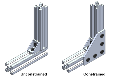
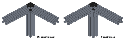
Presto! We can use this same technique to ensure that T-intersections are also fully-constrained.
Not too difficult, eh? Let’s try another one. In this next instance, we’re trying to prevent the profiles from rotating relative to the cube. Two additional corner brackets handle that issue. Once installed, they guarantee that all three extrusions stem out from the corner cube in a way that’s coplanar to the cube surfaces.
2. Measuring Tools to the Rescue
The redundant-connector method isn’t too difficult, right? Unfortunately, this method for constraining junction points will cost us an arm-and-a-leg in extra connectors. What’s more, those extra connectors are, in fact, redundant. In both cases above, the first connector, once tightened down, will hold the profiles in place. All additional connectors are redundant in that they don’ t prevent the junction from moving any more than the initial connector did. The benefit from using redundant connectors is that we don’t need to find that “sweet spot,” where the profiles exhibit all the geometric relationships we want, before we tighten them down. The redundant connectors force the profiles into the right spot with their geometric properties.
However, with the right measuring tools, we can toss out the need for redundant connectors by, instead, relying on our tools to do the job of finding the “sweet spots.”
Squaring-Up Corners
 Let’s start by locking down our right angles. For most of what we’re building, odds are good that the majority of our junctions intersect at right angles. This is likely the case since most vendors already have a host of connectors setup for doing just that: holding our profiles at right angles to each other.
Let’s say we’re looking to connect our profiles together at a nice T-intersection plate. Naively, we can just screw them in, but we’re subjecting ourselves to the possibility of misalignment. The solution? We need a reference of some sort. For us, that reference is a machinist square.
These machinist squares are essentially glorified right angles held to a very tight tolerance, somewhere between 0.0001 to 0.0008 inches (0.00254 to 0.02032 mm) for a modest set that wont break the bank. There’s no magic to using these. Simply hold it flush to the corner we’re interested in keeping square; then, gently tighten down the fasteners. Without much effort, we can guarantee a very high degree of accuracy across corners. Squaring up corners is, by far, one of the easiest operations we can perform to keep our gantry frame in-line with the design. Provided that we can readjust our connector setpoints, a few minutes with a machinist square can save us hours of potential redesign time.
Closing the Loop on Rough Cuts
Back when I assembled my first laser cutter frame from these profiles, I noticed a problem with the cuts. Right angles weren’t right angles! Like some cruel joke, the reality of I-have-no-idea-what-I’m-doing started to creep over my shoulder as I realized that my measuring tools just weren’t good enough. My frame was skewed beyond what my eyes could detect as erroneous.
A couple head-scratching weeks later, I became the proud owner of a set of Ebay-ed 40-inch calipers. With this nifty tool I could quickly measure the 0.4-mm difference between two parallel gantry frame components that were supposed to be identical in length. Well snap; my gantry frame was a giant parallelogram; I just couldn’t see it!
Buying a set of 40-inch calipers isn’t necessarily the solution to a square gantry frame. In fact, a machinist square from the above section should be more-than-sufficient to find frame misalignment and then correct for it. Nevertheless, a set of giant calipers will enable us to close the loop on our rough cuts and actually measure our longest profiles to a high degree of accuracy. For me, finding and fixing this problem with a better measuring tool has been a telling lesson that our resulting machine is no more precise that the tools we used to measure and align it.
3. Upgrading our Fab Equipment
Before we leave this section there’s one last culprit that will threaten the accuracy of our design: it’s our fabrication tools. Now, a host of folks online will tell us that cutting down extruded profiles is a bit like chopping wood–and it’s true! Hence, with the right blade, it’s actually pretty common to see folks cutting these profiles down to 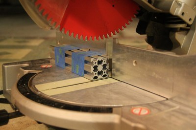 size with a chop saw.
To my fellow companions armed with chop saws, I must offer a word of caution about the quality of the resulting profile edge. First off, with the right blade, the cuts are, admittedly, very clean. The risk, though, comes in assuming the squareness of the cut. If you’re chop saw wont let you adjust the tilt and yaw angles of the blade, odds are good that those profile ends aren’t square.
So our chop saw cuts our part at the wrong angles; what’s the big deal, right? The problem with this method arises when we treat the butt ends of our profiles as references before tightening down their fasteners. I strongly recommend avoiding this practice unless the profile ends are measurably square with a machinist square. If they aren’t square, neither will the result angle be square if the chopped end is fastened down flat against any other part of the profile.
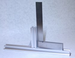
For clarity’s sake, I did just that in the image below: I chopped down an extrusion with my chop saw, butted it flush against another profile, and fastened it down with a T-plate connector. Can you see any issues? (Hint: zoom in)
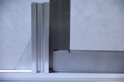
Here, this profile was chopped with a chop saw. Unfortunately, since I can’t control the tilt angle of my chop saw, all parts chopped with this tool will have a slight deviation from 90-degrees at their chopped end. If I fixture the profile end to the surface of the bottom profile, I’m effectively using the cut end as a reference. Since my reference is slightly off from the nominal 90-degrees, so too will my profile when it’s fixtured this way.
To fix this problem, if we must put our profiles together this way, our best bet is to finish off the ends with a milling machine.
Provided that the machine is aligned correctly and the profile is fixtured properly, we’ll get an angle that’s about as square as we can measure. I faced off the end of the same extrusion with a Taig micro mill, and as far as my measurement tools are concerned, it’s perfect.
Keep in mind that this solution only matters if we’re using the ends of our profiles as assembly references. At the end of the day, not everyone has access to fancy equipment like a fully blown milling machine–and we don’t necessarily need them. For most instances, we can handle slight imperfections by accommodating them in the design as we did in the first section. In that spirit, I could’ve easily fixed the problem by fully constraining the profile with a redundant corner bracket. Alternatively, we can rely on our measurement tools to provide us with the necessary references as we assemble parts together. Here, I could’ve easily loosened the T-plate connector and bumped the profiles flush against my square before tightening them back down.
I’ve done my best to make this guide a list of tips-and-tricks for getting accurate builds from these profiles, but it’s far from complete. If you’ve got stories from the trenches about precision builds, let us know what we’re missing in the comments. Happy hacking!


I must say that I have built quite a few 3D printers using V-slot, and it’s a very nice substitute for linear rails.
https://goo.gl/photos/gv87N4sFnPpEprF5A
Can someone recommend a good saw that can be adjusted to cut extrusion square?
I use my radial arm saw, with a blade specific for metal. It cuts a remarkably smooth flat surface with a slight pebbled surface finish.
It’s only limited by the right-angle accuracy of the saw, which I tune to less than half a millimeter over 10 inches. I cut from outside in (push the saw away from me, rather than pulling it towards me) to firmly force the metal piece into the fence while cutting.
Home Depot or Lowes has metal cutting circular sawblades for table and radial arm saws.
This link has pictures of the results:
https://hackaday.io/project/4689-improve-the-haber-process/log/21239-update-july-20
Cold saw.
“riff off of each other”? Rip off?
“RIff off” means to take inspiration from someone else’s work and then make your own thing based on it.
“Rip off” means to take someone else’s work wholesale or pass it off as your own.
There’s an argument to be made which of these more closely descrbies the various forms of T-slot extrusion.
For those that don’t know, a cold saw is a carbide tipped metal cutting saw blade vs a “hot” aluminum oxide type abrasive.
There is a lot that makes a saw good or bad.
I started by buying a 14 inch abrasive cutting disk drop saw. It cost about $140. It cut through aluminium (aluminum) like an oxy-acetylene through soft butter – not good, it more or less melts it’s way though and leaves a horrible finish.
Then I bought a 14 inch 120 tooth aluminium cutting TCT blade and that cost more than the saw did, just for the blade. Now it cuts through aluminium like a sharp knife through soft butter and leaves a near perfect finish apart from some angle inaccuracies because there are misalignments in the saw itself.
Here are the issues –
First up a metal cutting TCT saw is like 130 scalpels spinning at 3800RPM. If this blade come off in some way while spinning I wouldn’t be surprised to see it cut though a concrete wall like the wall wasn’t even there. Don’t “experiment” these things as human flesh has *not a chance* against a blade like this. It could cut right through a torso just as easily as it would cut through a finger.
An abrasive disk saws do things that a TCT blade should never do. You can pull an abrasive disk back up through the cut and even drop off the power when doing that. A metal TCT saw should cut and stay at the bottom until it stops and the cut material is removed so your going to want an electric break.
It’s important for a TCT saw to have not backlash between the motor and disk. Abrasive disk saws have huge backlash.
Here is what I realized in hindsight –
I wasted money by buying an abrasive cut off saw because I will have to replace that with a real TCT saw anyway.
This 14 inch blade and motor combination is way more than I need. It doesn’t even drom in RMP when I cut and takes no effort at all. A smaller setup would have been better for exreusion.
A plain drop saw is fine for the small extrusions that I use but won’t cut sheet. This isn’t a problen for me personally because I want to cut circles which means I need a scroll saw.
So what you need is –
A saw intended for use as a TCT metal cut off
With an electric break
With a square base or adjustable tilt / miter
And a fair amount of money lol, and accurate saw is going to cost.
I neither want to be in the path of a loose spinning non TCT circular saw blade with any body part. I don’t think the tungsten carbide makes any difference in contact with flesh.
The main difference is that carbide tipped blades are for more brittle and because of their design (carbide teeth attached to a steel body) if you cut wrong (for example slamming the saw into the workpiece) it can shatter.
80/20 uses 6105-T5 aluminum which is very comparable to 6061.
I have a bunch on order for a base for my Shapeoko3. (the 40 series uses m8 T-nuts which work really well with a m8 machinist hold down kit)
Another upside to using the industry standard products is the capability to provide cad files and have all parts machined for you if you require so. In my case this is beneficial in order to have all the holes drilled accurately and with minimal deviation from the prescribed locations as well as save my self all the extra time.
In the end it depends on your application and as a designer you should be selecting the proper materials based on the application that you plan to use extrusions in.
I would suggest that once you get your system in the state you want, weld those beam joints to eliminate the “wiggles”
Replace wiggle with warpage? not a great trade-off.
This would require the welding of aluminum and thus special TIG equipment – and welding skills.
Welding adds a lot of heat to the metal, which expands. The less-heated zones expand less, so forces build up between the different temperature zones.
Then the weld zone softens and melts, losing strength. This allows the non-melted metal to shrink.
When the molten zone cools to the point where it solidifies, it ‘resets’ to its current size. Then it shrinks as it cools to the final temperature.
Welded metal is going to warp.
What could home 3D printers become of true value for; rather than a hobby? .. I value machining equipment.. But now only foresee 3D printers being a fad, like the simple ‘Roomba’ vacuum robot… I’m most impressed by laser eye surgery equipment!
How would you make a (one-off) fan shroud without one?
Custom spacer pieces?
Sure, you could have injection molds made (only $10,000 or so per iteration)…
It’s another type of tool. Not good for everything, but great for some things.
Aluminium extrusions also suffer torsion twisting during manufacture. So a design may be unable to be machined flat without severe loss in material thickness. Thus, truly square structures can’t be corrected using hardware fasteners without deforming the design, or milled correctly without introducing localized weaknesses that cause bowing.
This means machines built with parts intended for non-precision design work are not great for linear rails. Accordingly, there are dozens of expensive products around that include rail inserts, but the fundamental design flaw remains true.
Most are almost certainly better off with a uniform material like steel box channel, that will not cause seriously weird phantom alignment problems. However, most consumers see a light-weight Aluminium machine’s shipping cost as another low-priced miracle (nope).
If you are building something for CNC that is not going to get torn down in a year, than hire a local water-jet, and machinist services. Your group will build something that is far more reliable, and ultimately less expensive for manufacture with fewer fasteners.
As a side note, some mechanical engineers have a weird obsession with extrusions. Seriously, you can’t rationally argue with them about how material meant for architectural safety enclosures may not be appropriate for precision machinery. They’ll kludge a pitchfork together while you get a coffee…
But consumers DEMAND their printers be quick, cheap, light, rigid, self aligning, require no service, sense everything, be able to run inside a house, not give off any fumes, run off 15A 120V, be operated by a child, be fully plug and play and also violate the laws of physics. They also should cost $500 or less.
Don’t forget they also want it to be made in america by well paid workers. All that for cheap should be easy to accomplish right?
Good point. It needs to also be made by hand as well by trained and skilled experts. Making things with machines hurt jobs and isn’t “real world craftsmanship”.
given that the cost of machining is variable depending on where you live as well as the numerous sizes in profiles, it seems rather short sighted to claim that aluminum extrusions are not right for any cnc project. In choosing the right materials for any design shouldn’t a designer weigh the cost, availability as well as functional requirements to determine which product to use? (in this question cost refers to raw material cost as well as machining cost)
as a side note, what do you mean when you say non precision work? can you give an example of the tolerances you are referring to? i would agree with you if your tolerances are meant to be with in 0.001 in, but if you are aiming at a 0.063 in precision then i dont necessarily agree (depending on what you are doing, i.e. wood or plastic milling)
Hah! Cutting up a bunch of 80-20 right this moment for some frames that are WAY too large for 80-20. Can’t believe they use this stuff. It looks nice, but there’s no stiffness.
curious, is it actually from 80/20 inc? also how big is the frame that you are making and which profile are you using?
Oh, I don’t know, we just call it all 80-20. Using 1×1’s make a box kite-like frame that’s eight feet long. I’d trust it to hold a poster board at most.. If I remember right, one of the sides, 8′ by 42 inches, doesn’t even have braces across the middle.
Why use all this shit when you can weld some steel together for less time and money.
Weight, and one still has to get everything aligned.
Welding requires prep in order for the weld to look like a weld. Also, it helps if you know how to weld. Also, good luck making a cube-like frame that doesn’t warp like a worm in agony…
Al extrusion is just cut to length and bolted together with off-the-shelf parts, that’s where it shines. Obviously, being made of extruded Al and joined with fasteners, it’s never going to be as strong, but it’s fast and easy to assemble.
Well, as an 10+ years of experience with welding it seems to me, its faster and easier (if you already have the setup (and I do)) to use steel and make it happen.
It takes time to learn to weld, welding equipment costs $$$ that can be hard to justify if not used often, there’s a problem with warping etc. that makes proper welding as hard as using profiles, alu extrusions can make an almost as stiff construction as the steel one at less weight.
Extrusions aren’t shit.
A smaller article with Ali parts list. Very useful if you aren’t in the U.S. and shipping costs due to weight are big http://www.absolutelyautomation.com/articles/2016/01/29/build-frame-mini-pilot-plant
Use 8020 here for frames and robotic camera mounts (the mounts move manually, the robotic camera is separate.).
Good stuff, and the stiffness over a number of feet is a factor, but put a right angle into the extrusion and just like an I-beam you’ve fixed the flex issue.
The trick of using more connectors to make a right angle is an useful tip.
Also want a cheap machinist square with absurd low tolerance? Use the door frame as a reference, or the laptop case, or a smartphone. Always invert the square to see if the square itself is really a square.
Mill a scrap piece of metal into a precise enough cube with a well-aligned milling machine. Cheaper than a machinist’s square if you already have a mill.
If you’re building with that 15mm square extrusion, a 123 block will be a good right angle reference, and you can make alignment pegs to screw into the edges and fit into the extrusion slots. Use a couple of C clamps to hold extrusion to block while tightening the corner plate.
I have a lot of door frames, few of which I’d trust to be square. In fact, I know with certainty that a few of them aren’t square since I had to adjust the doors they frame to fit so they’d close properly.
You can find adequate machinist’s squares for not much money. A 6 inch machinist square can be found new for under $15. Is it as good as a Starrett? Probably not. But I’d be willing to bet the difference in the cost of the two (about $185) that the difference in squareness is a lot less extreme than the difference in price.
I know it’s a safe bet though as I have both. I picked up a Starrett 6 inch machinist’s square at an estate sale for about $25. It had a bit of surface rust which was easily cleaned up. Using a B grade granite surface plate and a dial test indicator setup I was able to compare its squareness to the cheap square’s squareness. The difference wasn’t detectable. If there is a difference it’s less than 0.0003″ (the accuracy of my DTI with some slop thrown in for the non-tool-room-grade surface plate) over the length of the square. That kind of “slop” is far beyond acceptable for most applications and certainly for squaring up aluminum extrusion framing.
Maybe I got lucky. But I bet even cheap and bad squares are more accurate than most alternatives.
Use Uni-strut. It is much more heavy duty for large gantry stuff. http://www.dansworkshop.com/2016/04/large-gantry-cnc-router/ Way cheaper than 80/20, and it comes in 10-foot lengths.
How straight would you say uni-strut is? Not that extruded aluminum is known to be all that straight, but I’ve often considered uni-strut and wondered how it compares.
Quote:
The redundant-connector method isn’t too difficult, right? Unfortunately, this method for constraining junction points will cost us an arm-and-a-leg in extra connectors. What’s more, those extra connectors are, in fact, redundant. In both cases above, the first connector, once tightened down, will hold the profiles in place. All additional connectors are redundant in that they don’ t prevent the junction from moving any more than the initial connector did. The benefit from using redundant connectors is that we don’t need to find that “sweet spot,” where the profiles exhibit all the geometric relationships we want, before we tighten them down. The redundant connectors force the profiles into the right spot with their geometric properties.
End quote.
Well, I’ll be damned if I leave those redundant connectors at the junction points once everything is tightened! They are like scaffolding, once you got everything in shape, remove them and keep them in your set as tools, to be used for another build.
I wish this were true, as it’d make things a lot cheaper.
When constraining junctions with multiple connectors you’re not aiming for redundancy. Each connector constrains different beam to beam relationships. For example, if you have an inside L bracket, one that connects to one face of one beam, and the right angle face of a perpendicular beam on the same plane as the first, you cannot tighten that connector tight enough to ensure that the beams remain coplanar. Assuming one beam is fixed, any force applied to the other beam risks breaking the coplanar relationship of those beams.
When you add a connector that constrains another relationship (like the coplanar relationship of the beams) it’s not a redundant way of reducing the “angle slop”, it’s its own thing entirely. Does it reduce angle slop? Maybe, but only coincidentally. That’s not what the added connector is for. The first connector constrains the beam angles relative to each other, the second connector constraints the connectors to a single plane.
As far as constraining beam right angles is concerned I’ve found that the most effective connectors are the cam fasteners. When used on “single” dimensioned beams they work well to constrain beam angles. When using double cams (or butt fasteners) the constrain both angle, coplanar, and pitch/rotational relationships.
The downside is that they are expensive, and they require drilling flat bottomed, counterbored holes with a pricey tool.
No mention of laying the strut across itself in XYZ and using the extrusion to find its own square?
Seems a huge omission.
Last time I looked at Makerbeam and Openbeam they were quite a lot more expensive than the standard Item clones (e.g. kjn aluminium, or valuframe).
Good article anyway.
Another (maybe) helpful tip is to use weld nuts (http://www.jhpfasteners.com/images/categories/Tab%20Spot%20Weld%20Nuts.jpg) instead of the expensive insert nuts made by 80/20. A pack of 50 10-32 weld nuts is about $8.00!
This article is gold.
I am also wondering how much such an extrusion droops down when a load (let’s say the weight of a nema23 motor) is in the middle of a 1 meter section?