The best thing about owning a 3D printer or CNC router may not just be what you can additively or subtractively create with it. With a little imagination you can turn your machine into a 3D scanner, and using capacitive sensors to image items turns out to be an interesting project.
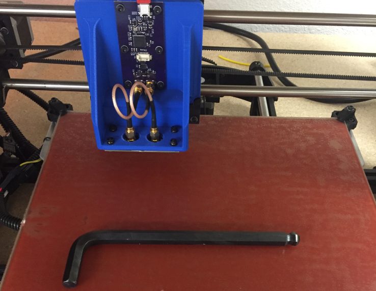
[Nelson]’s scanner idea came from fiddling with some capacitive sensors at work, and with a high-resolution capacitance-to-digital sensor chip in hand, he set about building a scan head for his printer. In differential mode, the FDC2212 sensor chip uses an external LC tank circuit with two plain sensor plates set close to each other. The sensor plates form an air-dielectric variable capacitor, and the presence of an object can be detected with high sensitivity. [Nelson]’s custom sensor board and controller ride on a 3D-printed bracket and scan over the target on the printer bed. Initial results were fuzzy, but after compensating for room temperature variations and doing a little filtering on the raw data, the scans were… still pretty fuzzy. But there’s an image there, and it’s something to work with.
Need a slightly more approachable project to get your feet wet with capacitive sensors? Maybe you should use your phone’s touchscreen as a 2D-capacitive scanner.
[via r/electronics]


For the record, this is the sort of thing I come to Hackaday for. Innovative new ideas.
According to DigiKey, the sensor is around $6, has a resolution of 28 bits, and a maximum input capacitance of 250 nF with an I2C interface.
Maybe someone could persuade him to put stuff up on .IO so we can follow the project and get alerts when there are updates?
I agree, exactly why I look at hackaday, to glean info on chips and projects that can go into the minds database for future possible solutions, maybe he has not perfected it yet but surely we do not want to see just perfected solutions, that would turn us into mere consumers.
What does 28 bits of resolution translate to in the final scan?
This approach needs more error correction and analysis before it’s really worthy of posting.
OTOH… release early, release often.
This. Again, I’d rather see a promising hack proving a point than anyone doing an advertisement for .
Well this is a blog about a log, not a submission to a peer reviewed journal.
> Well this is a blog about a log
Dear Liza!
I disagree. It’s about the concept, and the concept is pretty cool. Yes, the implementation needs improvements. But so did the first RepRaps. And see what we have now.
I wonder if this could provide some information about the internal structure of a sealed object. Certainly not an x-ray, but better than nothing.
wow, that is pretty impressive! I wonder if one could build something similar without the external capacity-to-digital converter (which is the largest cost contributor, here), in principle, by using the “time it takes to discharge a pin after toggling it from high output to low-input” techniques that are abundant in microcontroller touchbutton interfaces.
Sure, you might to need back on resolution – but I doubt the 28 bit resolution are helpful within a non-temperature, non-moisture, non-EM-controlled environment, anyway.
The sensor (a Texas Instruments FDC2212) does in fact behave a little different than just the aforemention discharge timer – it excites an external LC oscillator, and by varying that C, you’d vary that oscillator’s frequency – and that frequency is what it actually measures (and then calculate the capacity change back from that).
You can think of it (in fact, you must) as FM – the signal (here: the capacitance) modulates the frequency of a wave. In fact, analog receivers do exactly that to tune the receiver: they have adjustable capacitors with a knob that says “frequency”.
So, what you’d need to build to replicate this operational principle is some kind of a) LC resonator driver (aka “transistor”) and b)frequency detector – and that really shouldn’t be that hard, given that you can either use a ready made CMOS counter IC to decimate that frequency down to something your microcontroller can directly deal with, or actually use a microcontroller with a timer unit that can count the occurences of a rising edge within a fixed time (ST Micro ARMs do tend to have those, for example). In fact, unless you let your LC circuit oscillate at hundreds of Megahertzes (which might not be a good idea for EM compatibility/legal reasons), a reasonable fast-clocked microcontroller could probably do this even without any special hardware.
Then, you’d probably throw some minimal digital signal processing at it – average, or rather low-pass filter, the result, or throw a Kalman filter at the problem, modeling the oscillator’s period length as an effect of a linear system overlaid with Gaussian noise.
I’ve been thinking about something like this on a larger scale… Scanning a metal detector over a larger area to build up an image of what is underground.
You and me both.
My idea is autonomous rover with a linear array of coils at the front, far away from the electronics and rotating magnetic fields of the drive motors. Any really ‘loud’ spots get an orange disk dropped off.
A rover was where my thoughts went first. More recently I thought about a scanning head (like posted project) on a large frame to isolate those other sources of EM.
Rough surface scattering (the “inverse problem” in electromagnetics) is a very hard problem. We are lucky to make educated guesses with most techniques. You need high frequencies to get a small enough wavelength to resolve features, but then your data set blows up quickly. Also, a pulsed system (non-continuous-wave) is very, very helpful. You just aren’t going to get more than a blob, at best, with a metal detector, and even then only objects with mu other than 1 (ferromagnetocs).
The dataset blowing up isn’t really a problem for me, within a certain range of “blowing up”. I wonder about scanning with a ramped frequency system, such as using higher frequencies for increased resolution only where the lower frequencies have already returned a hit of some kind.
While not a bad idea, if the higher frequency data isn’t good enough to register a “hit” , what kind of additional data do you expect to get from it?
Objects might be transparent or absorptive at one frequency, opaque or scatter-ey at anther. While a broadband dataset is good, it probably won’t solve the resolution problem.
All valid concerns. My intuition is that one could use data from different frequencies at a given location to characterize material location/type/density/etc. in some way. This is all theoretical, as I haven’t started playing with the system.
I also wonder about techniques like what are used in super-resolution microscopy. There really is a lot of room for tech development in this area, if one were so inclined.
People do that with magnetometers for archaeology sites and get beautiful images.
The googlon is ‘magnetometer survey’.
Those are over relatively huge areas. The OP is trying to image small objects.
A capacitive sensor is going to be much better for dielectrics (say, plastics) than for metals. When mu is not equal to 1, you have to go back to Maxwell’s and check your assumptions.
Also, you’re probably measuring effective permittivity (epsilon_eff) so you might need an iterative post-processing step afterward to guess at the true epsilon and thus a sharper image.
Hate to reply to my own post, but another strategy would be to scan some test objects. Simple geometric shapes made of plastic. Then train a neural net with the input and output. This lets you skip a lot of the hard EM computation work which might require access to a cluster otherwise.
Are we April 1st already? Go read FDC2212’s specs. There is nothing in there about temperature being an important cause of reading error. So the room temperature correction factor is bullshit. As with the correction applied on the first grabbed image (substractig by the mean of the column, c’mon…). I guess this where we put LOL.
Indirectly, it’s true. A change in temperature results in a change in humidity (usually), which changes the permittivity of the air and thus it’s capacitance.