All other things being equal, signals with wider bandwidth can carry more information. Sometimes that information is data, but sometimes it is frequency. AM radio stations (traditionally) used about 30 kHz of bandwidth, while FM stations consume nearly 200 kHz. Analog video signals used to take up even more space. However, your brain is a great signal processor. To understand speech, you don’t need very high fidelity reproduction.
Radio operators have made use of that fact for years. Traditional shortwave broadcasts eat up about 10kHz of bandwidth, but by stripping off the carrier and one sideband, you can squeeze the voice into about 3 kHz and it still is intelligible. Typical voice codecs (that is, something that converts speech to digital data and back) use anywhere from about 6 kbps to 64 kbps.
[David Rowe] wants to change that. He’s working on a codec for ham radio use that can compress voice to 700 bits per second. He is trying to keep the sound quality similar to his existing 1,300 bit per second codec and you can hear sound samples from both in his post. You’ll notice the voices sound almost like old-fashioned speech synthesis, but it is intelligible.
While there’s something to be said for dead-bug construction, hot glue, and other construction methods that simply get the job done, it’s inspiring to see other builds that are refined and intentional but that still hack together things for purposes other than their original intent. To that end, [Li Zanwen] has designed an interesting new lamp that uses magnets to turn itself on in a way that seems like a magnetic switch of sorts, but not like any we’ve ever seen before.
While the lamp does use a magnetic switch, it’s not a traditional switch at all. There are two magnetic balls on this lamp attached by strings. One hangs from the top of the circular lamp and the other is connected to the bottom. When this magnet is brought close to the hanging magnet, the magnetic force is enough to both levitate the lower magnet, and pull down on a switch that’s hidden inside the lamp which turns it on. The frame of the lamp is unique in itself, as the lights are arranged on the inside of the frame to illuminate the floating magnets.
While we don’t typically feature design hacks, it’s good to see interesting takes on common things. After all, you never know what’s going to inspire your next hackathon robot, or your next parts drawer build. All it takes is one spark of inspiration to get your imagination going!
When you stuff a pair of Nixie tubes into a wristwatch the resulting timepiece looks a little like Flavor Flav’s necklace. Whether that’s a good thing or not depends on your taste and if you’re comfortable with the idea of wearing 200 volts on your wrist, of course.
As a build, though, [prototype_mechanic]’s watch is worth looking into. Sadly, details are sparse due to a computer issue that ate the original drawings and schematics, but we can glean a little from the Instructables post. The case is machined out of solid aluminum and sports a quartz glass crystal. The pair of IN-16 tubes lives behind a bezel with RGB LEDs lighting the well. There’s a 400mAh LiPo battery on board, and an accelerometer to turn the display on with a flick of the wrist.
It may be a bit impractical for daily use, but it’s a nicely crafted timepiece with a steampunk flair. Indeed, [prototype_mechanic] shows off a few other leather and Nixie pieces with four tubes that certainly capture the feel of the steampunk genre. For one with a little more hacker appeal, check out this Nixie watch with a 3D-printed case.
… I had a cheap Chinese drone that was broken, but its camera seemed to be operating and when I took apart my drone I found a small WiFi chip with a video transmitter. I (decided) that I will use this little circuit for a project and I started to buy and salvage the parts.
Being a tracked robot, it can negotiate most types of terrain and climb hills up to 40 degrees. It is powered by two 18650 lithium-ion batteries with a capacity of 2600 mAh and the remote control is based on the HC-12 serial communication module. You can control it with a joystick and watch the camera’s live-stream in a virtual reality glass. That’s pretty neat but it’s not all.
[Imetomi] also used a hacked Nacomimi Brainwave Toy to make a brain controlled version of his robot. The brainwaves are detected using sensors placed on the scalp. To actually control it the operator has to focus on the right hand to move right, focus on the left hand to move left, blink to move forward and blink again to stop. There is also an ultrasonic sensor to help navigation so the robot doesn’t bump into things. It’s not very precise but you can always build the joystick version or, even better, make a version with both controls.
In a recent posting called Liar’s 3D Printing, I showed you how you can print with multiple filament colors even if your printer only has one extruder and hot end. It isn’t easy, though, and a lot of models you’ll find on sites like Thingiverse are way too complicated to give good results. An object with 800 layers, each with two colors is going to take a lot of filament changes and only the most patient among us will tolerate that.
What that means is you are likely to want to make your own models. The question is, how? The answer is, of course, lots of different ways. I’m going to cover how I did the two models I showed last time using OpenSCAD (seen below). The software is actually really well suited for this hack, making it easy for me to create a framework of several models to represent the different colors.
About OpenSCAD
I’m not going to say much about OpenSCAD. It is less a CAD package and more a programming language that lets you create shapes. We’ve covered it before although it changes from time to time so you might be better off reading the official manual.
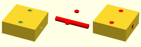
The general idea, though, is you use modules to create primitives. You can rotate them and translate them (that is, move them). You can also join them (union) and take the difference of them (difference). That last is especially important. For example, look at the callsign plate above. Forget the text for now. See the two holes? Here’s the OpenSCAD that creates that shape:
The cube “call” creates the base. The cylinders are the holes and the difference “call” is what makes them holes instead of solid cylinders (the first thing is the solid and everything after is taken away). One key point: instead of numbers, the whole thing uses (mostly) variables. That means if you change the size of something, everything will adjust accordingly if you wrote the script well. Let’s look at applying these techniques for multiple colors.
If you’re looking to control WS2812 (or Neopixel) LEDs using a microcontroller running at 3.3 volts, you might run into some issues. The datasheet tells us that a logic high input will be detected at a minimum voltage of 0.7 * Vcc. If you’re running the LED at 5V, this means 5 V * 0.7 = 3.5 V will be needed for the WS2812 to detect a ‘1’ on the data line. While you might get away with using 3.3 V, after all the specification in the data sheet is meant to be a worst case, it’s possible that you’ll run into reliability issues.
So usually we’d say “add a level shifter to convert 3.3V to 5V” and this post would be over. We even have a whole post on building level shifters which would work fine for this application. However [todbot] at CrashSpace came up with a nifty hack that requires fewer components yet ensures reliability.
For the Big Button project at CrashSpace, [todbot] used an ESP8266 running at 3.3 volts and WS2812 LEDs running at 5 V. To perform the level shift, a signal diode is placed in series with the power supply of the first LED. This drops the first LED to 4.3 V, which means a 4.3 V * 0.7 = 3.01 V signal can be used to control it. The logic out of this LED will be at 4.3 V, which is enough to power the rest of the LEDs running at 5 V.
This little hack means a single diode is all that’s needed to control 5 V LEDs with a 3.3 V microcontroller. The first LED might be a little less bright, since it’s operating at a lower voltage, but that’s a trade off [todbot] made to simplify this design. It’s a small part of a well-executed project so be sure to click-through and enjoy all the thought [todbot] put into a great build.
Today on Hackaday Dictionary, we’re going to talk about the two basic types of control systems: open-loop and closed-loop. We’ll describe the differences between them and explore the various advantages and disadvantages of each. And finally, we’ll talk about what happens when you try to draw a line between the two.
Control systems are literally all around us. They’re illuminating our rooms, laundering our unmentionables, and conspiring to make us late for work. Most of us probably use or interact with at least five control systems before we’re even out the door in the morning. Odds are you’re using a control system to read this article.
When we say ‘control system’, we’re speaking broadly. A control system is defined as any system that exhibits control over a function. It doesn’t matter how big or small the function is. A standard light switch is a simple type of control system. Flip it back and forth and the light is either on or off with no in between. Too bright? Too bad. There is no way to account for light intensity preference, use duration, energy output, or anything else.
Another common example in discussing control system theory is the clothing dryer. Set the timer on the dryer and it will run until time expires. Will it run long enough to dry everything without shrinking anything? The only way to know is to open the door and check.
Both the light switch and the clothes dryer are open-loop systems. The process is a straight line from start to finish, and they operate without concern for their output. Once the light switch is flipped to the on position, current will flow until the switch is reversed. The switch doesn’t know if the bulb is burned out or even screwed into the socket to begin with. And the clothes dryer doesn’t care if your clothes are damp or dry or totally shrunken when time runs out.
Stay in the Loop
In a closed-loop system, the process begins the same way it does in an open-loop system. But a closed-loop system has one or more feedback loops in place that can adjust the process. Sometimes the feedback will simply cause the process to repeat until the desired result is achieved.
Both of our open-loop control system examples above could easily be converted to closed-loop systems. A more advanced light switch might take input from a photo cell, or it could poll a motion detector and turn the lights off after a period of no detectable activity in the room. The clothes dryer could be improved with the addition of a moisture sensor. Since the humidity level in the dryer will change during the cycle, why not poll a DHT22 and re-run the process until a predetermined humidity level is reached? Then the dryer becomes a closed-loop system. No more reaching in and fondling the towels and shirt collars to make sure everything is dry. Well, at least in theory.
Some control systems exist in both forms. Traffic lights are a good example of this phenomenon. Some lights are open-loop and simply run on a schedule. Many more of them are closed-loop and will cycle differently depending on traffic flow or information received from other traffic lights. The really smart ones have Emergency Vehicle Preemption (EVP) receivers. This is the system that allows fire trucks and some other emergency vehicles to change the lights in their favor. A device in the vehicle strobes a specific pattern at the receiver module on the light post, and the light changes as soon as possible.
The main advantage of closed-loop systems is fairly obvious: using feedback means more and better control. But there are trade-offs. It’s almost impossible to deal with all the what-ifs in creating any system, and this generates unforeseen issues. They aren’t all bad, though. Maybe you’re sitting peacefully in the corner engrossed in a book, and the motion detector-driven lights shut off because you aren’t moving around enough. That isn’t ideal, but it’s easy enough to turn the lights back on and keep reading.
The unforeseen issues can be so much worse than sudden darkness. Case in point: robotic vacuum cleaners. Here you have a complexly closed-loop system to take care of one of life’s drudgeries. Should be awesome, right? Yes, but because it is blind to everything but its pre-programmed boundaries, it doesn’t know not to spread messes around.
A lot of closed-loop control systems look great on paper, but their imperfections become clear in execution. Take cruise control for example. Here is a system that’s better at its job than humans are. It will maintain the set speed until you hit the brakes or run out of gas. It will perform as intended whether there is a headwind or a tailwind or you’re towing a boat or transporting rowdy children. But cruise control isn’t aware of cliffs or guard rails or deer darting out in front of the car. Cruise control keeps its head down and does its job until it can’t go on.
Open-loop systems may not be as smart as closed-loop systems, but they often shine in their simplicity. For the most part, they do what you expect them to do. Light goes on, light goes off. And they are arguably more dependable since there are fewer things that can go wrong. Of course, a “simple” open-loop control system can mean a steeper learning curve. It’s not easy to learn to drive a manual transmission. But if you don’t know how to drive one, you’re missing out on some nice advantages, like the ability to push start the thing if you have to, and the option to downshift instead of pumping the brakes in icy conditions. So the question is this: is an open-loop system more valuable than a closed-loop system if it means having more control over the process? Does it depend entirely on the process in question?
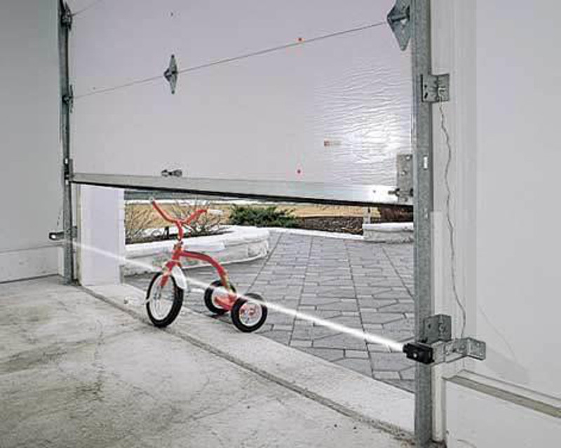
This tricycle is simultaneously safe and unsafe. Image via Apple Door
Open-Loop vs. Closed-Loop
So where exactly does open-loop end and closed-loop begin? The line seems clear for some systems, but muddy for others. How much feedback is enough to qualify? Add just about anything to a light switch and it seems safe to say that you took it from open- to closed-loop.
More often than not, the line between the two is blurry. Think of a motorized garage door. You push the button and the door either opens or closes. Push it again and the door moves in the opposite direction. Most modern garage doors have a fail-safe in place to stop the garage door in the event of an emergency. If the door encounters any resistance, it will stop and reverse direction.
The break beam detector is supposed to keep people and their tricycles from being crushed if they happen to be in the way while the door is closing. But it only works if the person or thing breaks the IR beam. There’s only one beam, and it sits about six inches off the floor. The motorized garage door system is actually quite limited because it has no positional awareness. It doesn’t know where it is on the track, it’s just going up and down blindly, waiting for input or resistance.
Not all doors can be counted on to stop if they feel resistance—I tested mine and it kept on going. So if I don’t pull far enough into the garage and then put the door back down, it might hit the protruding rear end of my hatchback. It’s in the way of the door closing, but it sits way too high to break the beam. So is the garage door really, truly a closed-loop system?


 For the