If you stuff a computer into a rack with a bunch of other machines, you’d better make it a tough machine. Server-grade means something, so using server parts in a project, like this high-wattage power supply using server voltage regulators, can take it to the next level of robustness.
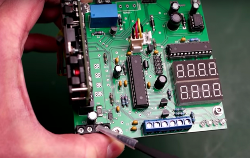
But before [Andy Brown] could build this power supply, he had to reverse-engineer the modules. Based on what he learned, and armed with a data sheet for the modules, he designed a controller to take advantage of all the capabilities of them and ended up with a full-featured power supply. The modules are rated for 66 watts total dissipation at 3.3 volts and have a secondary 5-volt output. Using an ATmega328, [Andy] was able to control the module, provide a display for voltage and current, temperature sensing and fan control, and even a UART to allow data logging to a serial port. His design features mainly through-hole components to make the build accessible to everyone. A suitable case is yet to come, and we’re looking forward to seeing the finished product.
Can’t scrape together some of these modules on eBay? Or perhaps you prefer linear power supplies to switched- mode? No worries – here’s a super stable unregulated supply for you.
https://www.youtube.com/watch?v=nAsno43i6HU
Thanks to [Orkhan] for the tip.


You can get a best-of-both-worlds with a combined switcher-linear hybrid supply. I did this for a Thunderbolt power supply (plug: I sell them on Tindie). You make a switcher with an output that’s just a little higher than the linear regulator’s drop-out voltage and then feed that into a 78xx/79xx style regulator.
The problem with linear regulators is that they dissipate power at the rate of Iout * (Vin – Vout). If you make Vin as close to Vout as possible, then you waste as little power (and make as little heat) as you can. Switchers can make arbitrary voltages with great efficiency, so they’re good at making primary supplies for linears like this.
In my testing, I’m getting < 10 mV P-P of noise and ripple from a supply rated for 800 mA @ 12v, 50 mA @ -12v and 500 mA @ 5v. You feed it with a 15W 15V wall wart (that is, itself, a switcher).
There exist a whole slew of test fixtures and testing methods for switching and or linear supplies. Definitely check out Jim Williams’ application design tips
That’s not really impressive… 10mV-ish is reasonable for a switcher. The cheap switcher I currently use as my main 3.3V supply (3A max) has 14mV ripple/noise or so (measured, not just a datasheet spec), and it’s wasn’t optimized for low noise at all! With a linear regulator you should be getting microvolts instead.
Then again, I don’t really see the point of using server modules. I can’t seem to find one under $20 + overpriced shipping. You can make a 3.3V 20A+ switcher from scratch for a lot less, without the reversing hard to source parts. You’ll even get a better efficiency out of it. If you can’t do it yourself with an intersil controller or such, there’s even automated tools to do it for you like webench…
First result out of webench (lazyness!) spit out a design using a TPS40304. The BOM is under $4 (all parts will be easy to source at modest prices for years). 25A max, 94% efficiency, fits in 279mm2, 600KHz switching freq (smaller inductors), and under 50mV ripple (if that’s too high then for $1 extra, a TPS53219A will get you under 10mV). That even comes with thermal simulations, pre-made PCB layouts (in case you never heard of that high dI/dt loop), a schematic, BOM and so on…
It is risky to use switcher directly. If the mosfet in the switching controller gets blown, it will pass down full voltage to the output. While on other hand blown out linear in most cases gets burnt out and blocks all the voltage. This is my personal experience with lm2xxx series switching controllers and lm78xx/1117 linear regulators.
It’s hard to generalize like that. It’s quite an uncommon thing to happen in a proper design, doubly so if you’re monitoring current/temperature. Lots of controllers are pretty smart too. That cheap TPS40304 has overcurrent protection so you shouldn’t destroy the mosfets so easily, and with soft-start the output at turn-on should be pretty clean — not that it’s ever been a problem for me. Since you’re talking about LM2xxx series, we’ve shipped something half a million LM2594’s and none of them has failed this way so far, and they’re not used in a very nice environment. As for linear regulators, I’ve seen LM317’s overheat and then crank their output voltage by like 80%.
There’s just so many other factors to consider, like transient response, EMI, efficiency, cost, thermal management, operating conditions (input voltage, temperature, etc), acceptable ripple, size, procurement (part lead times, distributor availability…) and much more. Everything’s always a compromise really.
I would not rely on this behavior in any case where a safe failure is desired or necessary. You can essentially use the same power semiconductors (BJTs or MOSFET) in switcher and linear designs, so there are the same failure modes. If you have a really expensive, safety critical or sensitve device to supply or test, you should take external overvoltage protection, up to a crowbar circuit (thyristor/SCR which blows a fuse in case of overvoltage.
And there is some starting jitters too.
I didn’t make it to impress. I made it to do a job. And I measured the results I quoted rather than just taking the word of the marketing department of a chip manufacturer.
meh
You can get better results by using LDO. One of the projects I have fiddled with was a regulated linear supply with low drop (0,3-0,7V) connected to adjustable buck regulator with its feedback taken from the output of linear stage and adjusted in such a way, that switching supply keeps output only 1,2V above the linear stage output. It was going to be 240W 30V/8A supply that dissipates only 10W in linear stage…
Care to share details about the feedback loop? Or more specifically, how to keep it from oscillating or going “boom”?
I have this perverted vision of building this switchmode PSU http://danyk.cz/reg60v_en.html and giving it a linear stage as well to smooth it out…
Even at a less modest dropout of 1.2V, at 40A, it’s still “only” 48W, which is still easily manageable with some obsolete PC cooling hardware from the scrap bin.
Basically you are asking for Loop Stability and Load Transient Analysis. Basically you have to model your system, look at the bode plot and design the feedback loop. Linear Tech’s LTSpice might be a good starting point as they have pretty decent models of their parts.
Best is to google for that and read up the app. notes and try to follow.
e.g. http://cds.linear.com/docs/en/application-note/AN149fa.pdf “Modeling and Loop Compensation Design of
Switching Mode Power Supplies”
It is not an easy subject, and there a lot of math involved to not be able to cover it in a few sentences or regurgitated youtube videos.
great modules… horrible socket… wount NOT want to “push” 20 Amps through such thing… even if using lets say 20 pins in parallel, thats 1 amp EACH pin… im sure people will chime in saying its a 2-3 amp per pin socket, but i disagree for “server’s sake” :P
That’s not the sort of socket these are intended to work with. You can see the retention clip indents in the side of the VRM, and the keying slot in the card edge. The proper sort of sockets will have a latch, keying, and extra wipers for the high current fingers. These modules have to deal with high current as well as sharp transient loads. But for hobbyist use as a bench supply, the card edge connector will probably be fine.
thank you, i understand now.
the connector used here is not the same as intended, well then that makes this a good hack, as it is working with a less expensive connector