Some years back, a museum asked me to help them with an exhibit a contractor had built for them. It was a wheel like the one on Wheel of Fortune, but smaller and mounted on the wall instead of the floor. You would spin the wheel, it would stop on some item, and a computer would play a short video about the item. Physically and mechanically, it was a beautifully built exhibit. The electronics, though, left something to be desired.
In principle, this is pretty simple computer task. Measure the position of the wheel, and when it stops moving, play a video based on the position. The problem was the folks who created the artistic mechanics didn’t think hard about the electronics behind it. Sometimes–but not often–the wheel would play the wrong video. Sometimes it wouldn’t play at all.
The Prime Suspect
My immediate suspicion turned out to be correct. I took the wheel off its mount to discover copper foil tape on the back of it. Each pie wedge had foil in different areas and there were two brushes in each area. When the wheel stopped, two of the brushes would be shorted together and the rest were open. The way they detected that was bizarre, but that wasn’t the problem. (It involved a cannibalized PS/2 keyboard.)
 There were quite a few pie wedges, so the device had multiple foil strips per wedge forming a 4-bit binary number. That is, each wedge encoded a number from 1 to 12 by using the presence of foil to denote a one and the absence, a zero. For example, the figure below shows a similar wheel with three bits. Moving clockwise from the top, the black mark on the outer track represents foil that forms a number 001. Then the foil forms 010, 011, and finally 100, which covers most of the wheel.
There were two problems. First, if the wheel was almost exactly half way between two zones, it was possible for two sets of brushes to make contact, even when only one should have made contact. The brushes were close together, not totally secure, and the foil wasn’t very precisely aligned. On the example wheel above, if you were right at the top, you could have the case where the brushes read 101, which isn’t even a legal combination on this simple wheel.
The other glitch occurred when the foil was on one half of a brush pair but not the other. This usually meant another brush was also half activated. The closer the brushes were on one track, the less likely this was, but there was always some probability that the wheel would stop just wrong.
The Answer
I made a few changes to the device. First, I changed the foil tape to paint and used an IR emitter and detector pair. I didn’t think the brushes were that reliable. But that alone wasn’t going to fix the problem. The entire system is basically a big homemade rotary position encoder. Real rotary position encoders use Gray code to prevent slight misalignments and border cases from being a problem. For some people, the term Gray code (named after [Frank Gray], the inventor) isn’t fancy enough. So they call it a binary reflected code. Do yourself a favor, and call it a Gray code. You don’t want to be like my old professor who talked about “maximizing the Boolean variable” when he meant “setting the bit to 1.”
Unlike, say, the ASCII code, there isn’t a single Gray code. The term refers to any sequence of binary numbers where each item has only one bit difference between itself and adjacent items. In academic-speak, the Hamming distance between each item is one.
Hamming Distance
The original wheel used sequential coding:
0000
0001
0010
0011
...
The Hamming distance between the first two items is one, but the next two items have a hamming distance of two because you have to flip two bits to go from one to the next. So this isn’t a Gray code. And don’t forget that when the sequence wraps around, the last entry and the first are also adjacent.
Consider this three-bit code with 4 items:
000
001
011
111
This isn’t a Gray code because the distance between the last item (111) and the first item (000) is three. One possible proper Gray code would be:
000
001
101
100
Of course, the code doesn’t have to start with 000, so an equally valid code is:
110
010
011
111
Common Sense
Because each adjacent item differs by only one bit, the edge cases work better with physical items like brushes or optical sensors. Assume you have two pie wedges on the wheel, C and D. If C is 011 and D is 100 (not Gray code), then it is possible at the edge to get 111 which would be some other item. But if C is 011 and D is 111 (as in the last example), moving from C to D will cleanly switch to D at some point. There won’t be any time when any other code is possible while moving from C to D.
 If you look closely at a rotary encoder disk, you can see the pattern. The wheel has eight pie slices. If you consider the three concentric rings, you’ll notice that on each slice a ring is either white or black and, looking at a neighbor slice, only one ring will be different. The image makes it clear why the first and last items on the list are logically adjacent. Since each neighbor differs only in one bit, it doesn’t matter if the disk spins clockwise or anticlockwise.
Why Gray? Why Reflected?
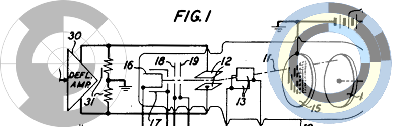
[Frank Gray] devised this coding scheme at Bell Labs and the patent dates to 1947 — the original circuit used vacuum tubes and a CRT. He didn’t call it a Gray code, but other patents dubbed it Gray code and the name stuck. The reflected name comes from one method of constructing a Gray code, and it appears in the original patent. Gray would later become semi-famous for working with [Herber Ives] to devise a scheme for color television that was compatible with black and white sets.
The reflection is part of a recursive algorithm for making a Gray code of any length. Start with the simplest Gray code: {0, 1}. Sure, it is just one bit, but the distance between each entry is one, so it is a Gray code. Now reverse (reflect) the list: {1, 0}. Still a Gray code. The next step is to put a zero in front of the first list numbers, put a one in front of the second list items, and then join the two lists: { 00, 01, 11, 10 }.
You can repeat that to get as many bits as you want. Three bits would start with the list {00, 01, 11, 10} and its reflection {10, 11, 01, 00}. The final code, then is: { 000, 001, 011, 010, 110, 111, 101, 100 }.
Of course, that’s just one possible Gray code. There are other useful variations with names ranging from monotonic Gray code to a “snake-in-the-box” code. You can’t make this stuff up.
We’ve seen a number of custom encoders over the years, and going with a full Gray code is often overkill. For instance, if you just care about direction and distance, you usually use a rotary encoder with quadrature output. If you just want to see how to read that type of encoder with an ARM processor, we just did one of those. But when the absolute position matters, and you care about keeping the transitions from becoming too messy, a Gray code is what you need.


Aurgh.
On the example wheel above, if you were right at the top, you could have the case where the brushes read 101, which isn’t even a legal combination on this simple wheel.The other problem was when the foil was on
On what?
I MUST KNOW!!
“There won’t be any time when a 111 (or any other code) is possible.”
Also needs fixing… (D is 111 at that point.)
On one half of a brush pair. That was just a zombie part of the next paragraph. I’ll delete it in a second ;-)
Err.
How well does the wheel work now?
Also, could it have been fixed by mechanically preventing it from being able to sit between two values with a spacer or other mechanical means? Logically like the wheel and contacts on “Wheel of Fortune”?
Yup, magnets, you can fix anything if you have enough magnets.
You can break a lot of things with magnets too. But then you can fix them using more magnets.
Oh man. Encoders with magnetic detents have some of the best ergonomics I’ve ever encountered. They have a really nice “settle” into each detent, there’s no mechanical snap or noise, and they last until the bearings wear out.
Think of a stepper motor’s cogging effect, on an encoder knob. There are projects out there which use unaltered stepper motors as rotary encoders, too. :)
This solution’s better. It’s impossible for it ever to give a wrong result. If it’s right on the edge of 2 segments, it reads as either one segment or the other. This is pretty much what Gray code is for.
Nothing stopping you putting detents on as well, the Gray code makes it bulletproof.
Why Gray code (patented 1947) and not Baudot code (patented 1874)? Why?
:o)
First, what was patented by Mr Gray was the method to generate any set of Gray code not a specific one. Secondly The Baudot code is only a Gray code when the alphabet is sorted, but there is no point sending a message of that sort. So when sending an abitrary Baudot message the Gray code property doesn’t hold, thus can’t be of any help in decoding the message.
Strong reasons indeed, thank you!
In fact I was wrong on the second point because first teletype were electromechanical. The codes were read on a drum by micro-switches, so the problem is the same as disc encoding. When the typist pushed a key the drum rotated until the code corresponding to that key matched. So Mr Baudot is indeed the inventor of this type of mechanical encoding.
“For some people, the term Gray code (named after [Frank Gray], the inventor) isn’t fancy enough. So they call it a binary reflected code.”
The “some people” you’re referring to here include… Frank Gray, who is the one who actually coined the term ‘reflected binary code.’ Because it’s just pretentious to name a coding scheme after yourself.
Well, I have (jointly) a patent on a telemetry synchronization protocol that uses something that is known as “The Williams Key” and I actively tried to stop that from happening. But people call it what they want anyway. Just because Frank didn’t want to use the name doesn’t make it any less pretentious to trot out a long name when everyone knows it as “Gray code.” In fact, I once was having the “how do you do your braces in C code” conversation with 3 or 4 other programmers years ago and one of them used K&R style braces because “that’s how the guys who wrote the language wanted us to do it.” I didn’t find that a compelling argument.
You’ve mentioned your patents before, why not do an article on them?
I’d like to see what it’s like to own a patent, did you earn much from it? Is it used?
Do you get to drink for free in certain bars?
Well, honestly they are pretty obscure. When I worked for a “very large company” there was some intangible benefit from getting patents. The dollar value to us as employees was pretty small (about $2,000). But they have all the rights. Presumably, if one of them made 100 million trillion dollars, they might have given me another $100 or something but not now that I’m gone from there nor are any of them in much danger of making even a little money.
So what is interesting is this. For many big companies (maybe or maybe not the big company I worked for) the possession of patents isn’t as valuable for licensing them. It is so you can use the “thing” without as much fear that someone will sue you. Plus lots of big companies shake hands and say “we can use all your bogus patents and you can use all of ours.” This is usually bad for the small guys, though.
Of the two patents I currently have (there are a few in the system that may or may not grant) one is very obscure and unlikely ever to see any actual use. The other is pretty practical and is used in a system where I was a chief engineer for awhile. It was enhanced by one of the implementors and he’s also named on that patent.
I still have to resort to bar bets to drink free.
I worked for a company with a very large patent library. Swapping licences was probably the biggest use, along with “well, if someone does come after us for violating something of theirs, we can probably find one of ours to threaten them with” – which usually ended in a license swap deal.
The project I worked on had some “genuine” patents (sadly never got my name on one!) where we’d developed the technology, and used it in our product. The patent was the only thing which stopped our customers from simply stealing the idea, which meant we could pay back the R&D which had invented it. That was a patent I could be proud to be involved in. On the other hand, I think we had a patent on something like “a play button on a GUI which changes to a pause icon when play starts” (may not have been exactly that, but that kinda thing), which had been granted long before computers were able to play music meaningfully.
Also anyone who doesn’t put the curly brackets on the same line as the header is bonkers.
bah, I find that darn near impossible to read in most realistic cases… especially if someone’s tabbing/spacing is unreliable.
With you on that. I want the brackets to line up vertically.
“that’s how the guys who wrote the language wanted us to do it.”
To people who used to write a lot of C, (cough, in the 80’s, cough), this used to be referred to as 1TBF for convenience. The “One True Brace Format” if you please. In a time when we were all stuck on terminals with 24 lines of text, it was very useful to NOT use an extra line just for a brace on its own (plus the inevitable extra whitespace to make the block stand out).
Back to the gray code discussion we came here for…
What is the timer contraption inside an old washing machine called?
Trouble
I feel the urge to share that this made me laugh hard.
Kontrapyion. Invented by a Russian named Chekov.
Lol, okay. +1
a Timer Knob
The examples in the article are lengths that are a power of 2, but the original problem needed a length of 12. I would like to know how the author set it up.
I was able to come up with some easy ways to make arbitrary length Gray codes for a rotary encoder. The first rule is that you can’t have an odd number of states. This is because to get back to the original state every flip of a bit on must have a corresponding flip to off, so there has to be an even number of states.
The second is that you can make a non-power of two pattern in n/2 bits. So if we want 6 states we can do it in 3 bits like this:
000
001
011
010
110
100
Notice how the ones move from right to left. Now there might be a better way to do this part
The third is that the length of a pattern can be doubled by duplicating each pattern and then adding an extra bit with the sequence “0110011001100….”. So with our previous example we start by duplicating each pattern:
000
000
001
001
011
011
010
010
110
110
100
100
And then we add in the extra bit
000 0
000 1
001 1
001 0
011 0
011 1
010 1
010 0
110 0
110 1
100 1
100 0
So with this scheme, a Gray code with N states, where N = 2^(a+1) * b and a >= 0 and b is odd, can be done in a+b bits. And with our example 12 = 2^2 * 3, so a = 1 and b = 3 and a+b = 4 bits. but if N was 14 it would take 7 bits (14 = 2^1 * 7)
Can any of yall do better?
Yup, it is trivial for all even cases – just use the appropriate-width slice centered to the gray code middle:
8-bit gray code:
0: 000
1: 001
2. 011
3: 010
4: 110
5: 111
6: 101
7: 100
6 numbers in the center:
1: 001
2. 011
3: 010
4: 110
5: 111
6: 101
Still a gray code, since 101 -> 001 has only one bit difference.
“Yup, it is trivial” – i.e. the power-of.two gray code can be trivially shortened to any multiple-of-two gray code.
…
4 (10): 0010 0110 0111 0101 0100 1100 1101 1111 1110 1010
4 (12): 0011 0010 0110 0111 0101 0100 1100 1101 1111 1110 1010 1011
4 (14): 0001 0011 0010 0110 0111 0101 0100 1100 1101 1111 1110 1010 1011 1001
4 (16): 0000 0001 0011 0010 0110 0111 0101 0100 1100 1101 1111 1110 1010 1011 1001 1000
I have a ruby script that gens these out to whatever you need.
Nice!! And the disk then can be divided into 6 slices of pie!.
Nitpick, but you want to concatenate the reflected lists, not interleave (that would be bad…)
I had already fixed that before I saw this comment. I think that must have been an editor slip because I don’t remember writing that. Then again, I am getting forgetful, if I remember….
This topic was always going to be a Gray area…
Nice article, especially with the motivating anecdote of making the display wheel work.
Hear, hear!
More of these, please, and less metric vs imperial or Edison vs Tesla (or any other A vs B) clickbait BS.
Or, you know, just straight-up hacks would also be good.
Also fewer “Scrap box ” articles that assume you have some highly-specialized components just lying around.
The toehr day they had this:
“http://hackaday.com/2017/01/18/a-no-solder-scrap-bin-geiger-counter-for-15/”
Which would cost a hell a lot more than $15 to actually make since you’d need the tube itself (they are quite rare and expensive even if you can find one), and then assumes that you have a multi-meter that can measure high voltages (requires 400+ volts to operate).
I have no problem with the assumption that I have a soldering gun, a millimeter, and other basic tools and parts like a screwdriver set or 1/4W 4.7k resistors; but assuming I have a soviet-made Geiger Tube is way too much to assume.
Is a millimeter a really small multimeter?
Autocorrect on mobile sucks. You can accidentally change words as you scroll around with no warning.
And I completely agree with [CA].
I could make a lot of things for only 15 dollars, if the stipulation that connecting an old computer to an old camera and a broken keyboard using 15 dollars worth of new USB cables…
If it is a metric multimeter, then it is 10 millimeters (just move the decimal point).
My multi-meters all* are capable of measuring 600V AC and DC and given that neither are professional versions I don’t think measuring 400+ volts would be problematic. Could be wrong of course.
(* I have two)
“You don’t want to be like my old professor who talked about “maximizing the Boolean variable” when he meant “setting the bit to 1.””
You can’t argue that it wasn’t an effective teaching device, if you have no trouble remembering it after all these years =P
Well it was a Master’s level course, so I would assume everyone knew what setting a bit to 1 meant already. I hope.
Though, it may be useful in the case of indicating that you’re talking about the variable itself, rather than, say, the pin (which may be active-low)…
Great example of where Gray Code is useful.
Even then I would just say asserted.
Nice article, but how about some techincal details on the actual hardware and sensor. Do you have the emitter and receiver on the same side? Do you look at just a single spot and how does it handle the edit case where the dividing line between a light and dark section happens? Or does that not matter because it’s not a valid Gray Code and so it’s ignored?
Looking at your Black and Yellow example, do you have the detector at the twelve o’clock posistion, reading all four pairs of concentric circles to decode the result?
Thanks,
The edge case doesn’t exist. The whole point of Gray code is that only one bit transitions between valid states. Either it’s “this” valid state or it’s “that” valid state, but there are no invalid states in between.
I realize that the entire purpose is to avoid funky states. My real question is the placement and number of sensors. If I goto the neat web site pointed out elsewhere in the thread to generate an SVG graphic, and enter 360 degrees and 4 states. How many sensors and what placement do I need? I assume I just need two sensors, BOTH at the twelve o’clock postition, with on on each ring. Correct? The web site is:
http://engineering.olkha.com/gray/
for reference. And I would assume the four states are then at the 45 degree offsets ( 2, 5, 7, 10 hour locations) for each of the four values.
That’s my question.
John
Yes, with 360 degrees and four states you get two rings of encoded position data. Absolute “twelve o’clock” isn’t so important, but being on the same radial line is critical for this code ring configuration. (Be aware there other ways to make the code ring that don’t use the sensors on the same radial line.) And yes, you need one sensor for each ring of code.
As to the black and yellow example in the article, yes the sensors are on the same radial line decoding the result. But there are only three rings of code data here.
I made checkbox “[v] Mark sensors” to light up positions for sensors.
I made checkbox “[v] Mark sensors” to light up positions for sensors.
Cool, but only shows ’em after you change a value elsewhere.
Handy tool!
Is it just me or do these patterns speak of fractals?
Yea, it looks like fractal.
(i have fixed some to show sensors without changing other values, must to be ok now. I use fireox.
There is a website generating the encoder pattern as scalable vector graphics *.svg
http://engineering.olkha.com/gray/
Man that would have saved me some time.
How did you found it? I made it just yesterday.
The author of the article found me ;-)
It was a comment to my video about the sensor arrangement on a quadrature encoder:
https://www.youtube.com/watch?v=dPBKTZw_xi4
Oh! Yea! I’m actually did not expect to such immediate reaction. But thanks :-)
Thank you for creating the helpful web application!
Notice how in the last picture in the article, the innermost and middle rings are identical, just rotated 90 degrees; this means you can make any N-bit gray code with N-1 rings (for N>1, obviously), by placing two detectors at a 90 degree angle on the same ring. Unfortunately, this only works once, so you can only save a single ring.
Such patterns are still widely used in industrial automation and embedded systems; the Hall effect sensors in a BLDC motor, for example, follow the same pattern; 3 sensors give 6 valid states, where 000 and 111 are invalid.
Nice observation, thanks for pointing it out!
I was taught (at work, not at school) that there was a class of codes called “monostrophic” (because only one bit changes at the time), and that *the* Gray code was one instance.
Later, I worked for a company that made very-high-resolution angle encoders. They were not optical, but used wipers on a copper pattern. I reported to the guy who held the patent on the “Datex Cyclic Code” which was a monostrophic code that translated easily to read out in degrees-minutes-seconds (this was way before everything had a microprocessor in it). Their biggest encoders were about two feet across, and were good to 24 bits. They were the original encoders used on the big dishes for NASA’s Deep Space Network.
Oh, wow. Are there photos of such a thing? I couldn’t find anything with a quick search, and this seems like one of those niche artifacts of the pre-microcomputer era that might easily be lost to the sands of time.
And have you heard of Single Track Grey Codes?
http://techref.massmind.org/techref/io/sensor/pos/enc/greycodes.htm
To quote Keanu Reeves, “WHOOOOOA!”
Agreed. Great info ’round there.
Also, a link from there to vernier scales. And somehow I never thought to use regular ol’ quadrature with a low-res graycode for quick “homing,” and high precision, thereafter. And, if I understand correctly, discussion about using e.g. three sensors with quadrature-encoding to increase resolution further…
(hey, digital-anaquad! https://hackaday.io/project/9984-anaquad).
I’m actually somewhat surprised that nobody has mentioned the most practical, day-to-day use for Gray codes: when you have a problem with multiple variables, changing them using a Gray code list means you A) only ever change one variable at a time and B) you never skip or duplicate a particular combination of variable settings.
Are we talking “boolean variables” here, or is this a general-purpose math thing?
General purpose. *Extremely* general purpose. As in ‘I have 11 herbs and spices. What is the tastiest combination for chicken?’ (That particular example would a ‘base-n’, rather than ‘base-2’.
Thanks for the article. The One-track encoder (from the links in the article) is now my favourite!!!
I just realized something. If you have, say, 4 gears connected serially, each of which has 8 bits of resolution, and each gear is down the chain has an 1:8 reduction in size (so that, in the time it takes the first gear to change values, the next has completed a rotation), altogether they will equal 32 bits of resolution for the first gear (Just mention me on the patent, and treat me right. :grin: ).
Does that make sense, or am I missing something?
I think you’ve just invented using cogs as a counter. As long as the guy at the patent office hasn’t heard of Blaise Pascal, you’re on your way.
Well, I wasn’t thinking of that, and I’m not conversant with how his calculator actually works, so I don’t know if we are talking about the same thing. I suspect not, though.
I remember there was some link to the Karnaugh Mapping technique?
I think I realised something. Correct me if I’m wrong but this Gray encoding gives a flaw or maybe an exploit. As far as I understand the possibility of value 0000 is lesser than 0001 (if they are next to each other). Is this right or am I misunderstanding the essence of this encoding?