The ATtiny85 microcontroller doesn’t have all that much of anything: 8 KB of flash, an 8-bit architecture, and only eight pins (three of which are taken up with power and reset duties). And that’s exactly what makes it a great fit for tiny little projects.
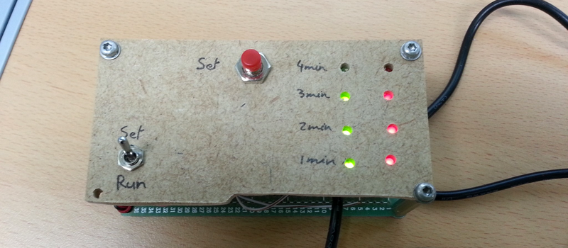
[Mimile]’s Tea Timer has a switch, a button, eight LEDs, and a buzzer. Flip the switch to “set” and button presses run through the desired steeping times. Flip it to “run” and you’re timing. The LEDs blink and the buzzer plays “Tea for Two” in squawky square waves. Wonderful!
But wait, how to control all of this I/O with just five pins? With one pin each for the two switches and one for the buzzer, that leaves only two pins for the eight LED display. [Mimile]’s fun solution is to use a binary counter (a 74HC393) and the remaining two lines to count and reset. That means toggling a pin very fast 255 times to light up all the LEDs. That’s a bizarre way to go, but we like it!
Hackaday has proven unable to resist the siren song of the ATtiny85. Whether teaching it to swear, to speak I2C, or to transmit analog TV signals, there’s just something about this cute little chip that invites you to test your mettle.


I have made a tea timer that control the dipping too using a PIC16F1703
demo: https://youtu.be/FAm9IDIoFMc
I boldly predict an ATTiny85 (or perhaps an 8 pin limit) Hackaday contest…
Hell yes!! Pic10F. :-). Awesome idea!!
Outstanding!
Instead of a 74HC393 counter, you could also use a 74HC164 shift register, which would only require 8 clocks to drive the outputs. And if you didn’t want glitches you could use a 74HC595, with an RC filter on the clock so that a short clock pulse would shift a bit, and a long clock pulse would load the register.
For anyone wanting to see more about this, http://romanblack.com/shift1.htm has some great documentation about how to use shift registers with only a single pin for applications like this.
Charlieplexing would require 4 pins for a maximum of 12 LEDs.
The schema shows pins 1 and 7 used to drive the speaker, where only one is needed. You can drive the speaker through a capacitor in series from one pin.
Likewise, you can read two buttons with one pin. There are various ways, a simple one would be an RC delay with the switches changing the R component.
Those changes would allow you to ditch the counter chip entirely and drive everything straight from the chip.
I’m not familiar with Kicad, but I think both pin 1 and the right side of the pot are unconnected.
I interpreted it as such because the line has the number 1 and a little X on it to mark a cut connection.
In any case, if it’s unconnected then so far so good. One free pin.
It’s easier than that. Each pin of the ATTinyx5 is usable as an ADC input. So you configure a resistor ladder so each button returns a different voltage. Reading the ADC will yield differing values. If you pick the values particularly carefully, you can actually use individual bits in the ADC result to represent the buttons, so things like chording still work.