See Satellites With A Simple Radio Telescope

Have you got a spare Dish Network antenna lying about? They’re not too hard to come by, either curbside on bulk waste day or perhaps even on Freecycle. If you can lay hands on one, you might want to try this fun radio telescope build.

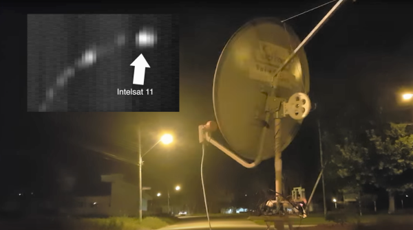
Now, don’t expect much from [Justin]’s minimalist build. After all, you’ll be starting with a rather small dish and an LNB for the Ku band, so you won’t be doing serious radio astronomy. In fact, the BOM doesn’t include a fancy receiver  – just a hacked satellite finder. The idea is to just get a reading of the relative “brightness” of a radio source without trying to demodulate the signal. To that end, the signal driving the piezo buzzer in the sat finder is fed into an Arduino through a preamp. The Arduino also controls stepper motors for the dish’s azimuth and elevation control, which lets it sweep the sky and build up a map of signal intensity. The result is a clear band of bright spots representing the geosynchronous satellites visible from [Justin]’s location in Brazil.

Modifications are definitely on the docket for [Justin], including better equipment that will allow him to image the galactic center. There may be some pointers for him in our coverage of a tiny SDR-based radio telescope, or from this custom receiver that can listen to Jupiter.

Continue reading “See Satellites With A Simple Radio Telescope”

Before There Were Nixie Tubes, There Were Edge-Lit Displays?

We’ve seen a bunch of replacements for nixie tubes using LEDs and edge-lit acrylic for the numbers. But one of the earliest digital voltmeters used edge-lit Lucite plates for the numbers and a lot of incandescent lamps to light them up.

[stevenjohnson] has a Non-Linear Systems Model 481 digital voltmeter and he’s done a teardown of it so we can get a glimpse of the insides. Again, anyone who’s seen the modern versions of edge-lit numeric displays knows what they are: A series of clear plastic plates with numbers (or characters) etched into them, each with a light source beneath them. You turn one light on to light one plate, another to light another, and so on. The interesting bit here is the use of incandescent bulbs and the use of sequential relays to cycle through the lights. The relays make a lot of racket, especially with the case open.

[stevenjohnson] also notes that he might have made a mistake opening up the part of the machine where the plates are stored as it took him a bit to get the plates back in place and back in the unit. We’d imagine it was pretty loud if you were taking a lot of measurements with this machine, although it looks great inside and, obviously, the idea is a pretty good one. Check out this edge-lit nixie tube display or these edge-lit numeric modules.

[via boingboing]

Continue reading “Before There Were Nixie Tubes, There Were Edge-Lit Displays?”

Adding Buttons To The ESP-12 – The Cheat Way

[sorki] had an ESP-12F and wanted to play with nodeMCU, but found they were lacking buttons for reset & flash. We’ve all been there – mucking about with a project on a breadboard, trying to save the time required to solder up a button by shorting pins with wire or bending component legs to touch. This either doesn’t work or ends up bricking the microcontroller when it inevitably goes wrong. [Buger] found a tidier solution to adding buttons to the ESP-12F with the minimum of effort.

It’s the spirit of deadbug applied to buttons. One side of a piece of wire is soldered to the pin needing to be pulled down. Component leg offcuts are ideal for this. The other end of the wire is bent up and left to float over the metal shield of the ESP-12, which is connected to ground. When you want the pin to go low, press the wire into the shield, grounding it. Let it go, and the pin returns high again, assuming your pullup resistors are all in order.

It’s a quick hack that’s much more robust than trying to hold two ends of a piece of hookup wire in place. It’s also still easier than trying to find a tactile switch solder leads to, and you don’t end up having it hanging off the board either.

For deadbug construction taken to an impressive conclusion, check out this clock built out of discrete components.

[Thanks to Richard Marko for the tip!]

Soda Bottles Used As Heat-Shrink For Wood Joinery

Nobody is likely to confuse it with the beautiful joinery that makes fine furniture so desirable. But as a practical technique, using plastic bottles as heat-shrink tubing for composite joints is pretty nifty, and the pieces produced are not without their charm.

Undertaken as an art project to show people what can be done with recycled materials, [Micaella Pedros]’ project isn’t a hack per se. She started with bottles collected around London and experimented with ways to use them in furniture. The plastic used in soda and water bottles, polyethylene terephthalate (PET), turns out to shrink quite a bit when heated. Rings cut from bottles act much like large pieces of heat-shrink tubing, but with more longitudinal shrinkage and much more rigidity. That makes for a great structural component, and [Micaella] explored several ways to leverage the material to join wood. Notches and ridges help the plastic grip smoother pieces of wood, and of course the correct size bottle needs to be used. But the joints are remarkably strong – witness the classic leaning-back-in-a-chair test in the video below.

Its aesthetic value aside, this is a good technique to file away for more practical applications. Of course, there are plenty of ways to recycle soda bottles, including turning them into cordage or even using them as light-pipes to brighten a dark room.

Continue reading “Soda Bottles Used As Heat-Shrink For Wood Joinery”

The Latest In 3D Printed Part Smoothing: Use A Brush

Part smoothing for 3D printed parts, especially parts printed in ABS, has been around for a while. The process of exposing an ABS part to acetone vapor turns even low-resolution prints into smooth, glossy 3D renderings that are stronger than ever. The latest improvement in part smoothing for 3D printed parts is now here: use a brush. Published in Nature‘s Scientific Reports, researchers at Waseda University have improved the ABS + acetone part smoothing process with a brush.

According to the authors of the paper, traditional filament-based printing with ABS has its drawbacks. The grooves formed by each layer forms a porous surface with a poor appearance and low rigidity. This can be fixed by exposing an ABS part to acetone vapor, a process we’ve seen about a million times before. The acetone vapor smoothing process is indiscriminate, though; it smooths and over-smooths everything, and the process involves possible explosions.

The researcher’s solution is a felt tip pen-like device that selectively applies acetone to a 3D printed part. Compared to the print over-smoothed in a vat of acetone vapor, more detail is retained. Also, there’s a ready market for felt tip pens and there isn’t one for crock pots able to contain explosive vapor. This is, therefore, research that can be easily commercialized.

Say It With Me: Aliasing

Suppose you take a few measurements of a time-varying signal. Let’s say for concreteness that you have a microcontroller that reads some voltage 100 times per second. Collecting a bunch of data points together, you plot them out — this must surely have come from a sine wave at 35 Hz, you say. Just connect up the dots with a sine wave! It’s as plain as the nose on your face.

And then some spoil-sport comes along and draws in a version of your sine wave at -65 Hz, and then another at 135 Hz. And then more at -165 Hz and 235 Hz or -265 Hz and 335 Hz. And then an arbitrary number of potential sine waves that fit the very same data, all spaced apart at positive and negative integer multiples of your 100 Hz sampling frequency. Soon, your very pretty picture is looking a bit more complicated than you’d bargained for, and you have no idea which of these frequencies generated your data. It seems hopeless! You go home in tears.

But then you realize that this phenomenon gives you super powers — the power to resolve frequencies that are significantly higher than your sampling frequency. Just as the 235 Hz wave leaves an apparent 35 Hz waveform in the data when sampled at 100 Hz, a 237 Hz signal will look like 37 Hz. You can tell them apart even though they’re well beyond your ability to sample that fast. You’re pulling in information from beyond the Nyquist limit!

This essential ambiguity in sampling — that all frequencies offset by an integer multiple of the sampling frequency produce the same data — is called “aliasing”. And understanding aliasing is the first step toward really understanding sampling, and that’s the first step into the big wide world of digital signal processing.

Whether aliasing corrupts your pristine data or provides you with super powers hinges on your understanding of the effect, and maybe some judicious pre-sampling filtering, so let’s get some knowledge.

Continue reading “Say It With Me: Aliasing”

The Hard Way Of Cassette Tape Auto-Reverse

The audio cassette is an audio format that presented a variety of engineering challenges during its tenure. One of the biggest at the time was that listeners had to physically remove the cassette and flip it over to listen to the full recording. Over the years, manufacturers developed a variety of “auto-reverse” systems that allowed a cassette deck to play a full tape without user intervention. This video covers how Akai did it – the hard way.

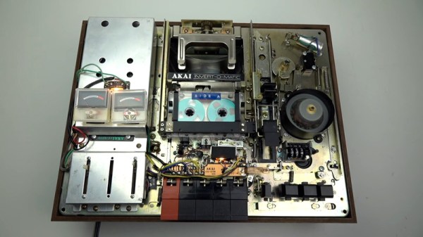
Towards the end of the cassette era, most manufacturers had decided on a relatively simple system of having the head assembly rotate while reversing the motor direction. Many years prior to this, however, Akai’s system involved a shuttle which carried the tape up to a rotating arm that flipped the cassette, before shuttling it back down and reinserting it into the deck.

Even a regular cassette player has an astounding level of complexity using simple electromechanical components — the humble cassette precedes the widespread introduction of integrated circuits, so things were done with motors, cams, levers, and switches instead. This device takes it to another level, and [Techmoan] does a great job of showing it in close-up detail. This is certainly a formidable design from an era that’s beginning to fade into history.

The video (found after the break) also does a great job of showing glimpses of other creative auto-reverse solutions — including one from Phillips that appears to rely on bouncing tapes through something vaguely resembling a playground slide. We’d love to see that one in action, too.

One thing you should never do with a cassette deck like this is use it with a cassette audio adapter like this one.

Continue reading “The Hard Way Of Cassette Tape Auto-Reverse”