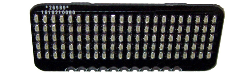
If you need a very thin, low power display that doesn’t use a whole bunch of pins on your microcontroller, [bobricius] has just the thing for you. His entry to the Hackaday Prize this year is a Charlieplexed LED display. With this board, you can drive 110 LEDs using only 11 GPIO pins.
Charlieplexing is a bit of a dark art around these parts. That’s not to say the theory is difficult; it’s really just sourcing or sinking current from a GPIO pin and arranging LEDs unparallel to each other. The theory is one thing, implementation is another. To build a Charlieplexed LED matrix, you need to go a bit crazy with the PCB layout, and god help you if you’re doing this point-to-point on a perf board.
Somehow, [bobricius] managed to fit 110 LEDs on a PCB, all while managing to break out those signal wires to a sensible set of pads on one side of the board. Only eleven pins are required to drive all these LEDs, making this project a great foundation for some very cool wearables or other projects that require a bright, low-res display.
Since [bobricius] can put 110 LEDs on a small board, he can obviously take LEDs away from that board. That’s what he did with his cut down version designed to be a clock. Both are great little boards, and the perfect solution for tiny displays for low-pin-count micros.


Remember some years ago hackaday featured a theardown and reverse engineer of a chinese led badge sign http://s.click.aliexpress.com/e/NZBmYjE that is powered by 3v coin cell. Havn’t reversed engineered it to see if is charlieplexed or mulltiplexed using shift register or dedicated IC. The page was in French, but ver detailed ( schematics, pictures ) so probably you won’t need to translate it: http://www.digitalspirit.org/wiki/projets/ledmatrixhacking
Thanks for writing. I just want add that this reduced display is used here https://hackaday.io/project/18895-hyperwatch-slim-motion-activated-led-watch
Full version of display is used here https://hackaday.io/project/15606-diy-gsm-arduino-fr4-cell-phone and https://hackaday.io/project/19597-pycard-jean-luc-pythonarduino-in-card-shape
Or you can just spend a couple bucks on a IS31FL3737 to have 144 charlieplexed LEDs (or 48 RGB), with PWM control, breath modes, de-ghosting, LED diagnostics and all… It only uses a couple MCU pins too (I2C controlled, so the pins can be shared). There’s options for 96 and 192 LEDs too. Sorry, but just simple LEDs onto a PCB is quite a weak entry.
Hacking at away or spending moneys… hmmm
Using 11 GPIO pins and coding for hours, or truly splurging all of $2 for an overall far better solution that works out of the box, which also frees up to 11 pins of the MCU, potentially saving more than $2… hmmm
For my is priority have full control on consumption, there is no problem make host board with any interface chip.
Use IS31 chip with only one suplier, QFN package is not for my
These are handy for other projects.
Way back when I used a similar DIL chip to make an LED electric fire by shifting colour patterns (ended up using red wide angle LEDs) and this worked fairly well to replace the troublesome bulbs which kept blowing frequently.
The big problem was that the LEDs were fully on or fully off so it flickered a bit.
Through the coloured perspex it looked half decent, alas the unit got “recycled” by someone because they couldn’t find the mains adaptor.
If I attempted this again it would reuse old LED backlights from TVs as they are free from old broken panels.
“unparallel”
Not parallel?
Please don’t do this.