We’re all used to touch pads on our laptops, and to touch screens. It’s an expectation now that a new device with a screen will be touch-enabled.
For very large surfaces though, touch is still something of an expensive luxury. If you’re a hardware hacker, unless you are lucky enough to score an exceptional cast-off, the occasional glimpse of a Microsoft PixelSense or an interactive whiteboard in a well-equipped educational establishment will be the best you’re likely to get.
[Adellar Irankunda] may have the answer for your large touch board needs if you aren’t well-heeled, he’s made one using the interesting approach of surrounding the touch area with an array of infra-red LEDs and photo transistors. By studying the illumination of the phototransistors by different LEDs in the array, he can calculate the position of anything such as a pointing finger that enters the space. It’s an old technique that you might have found on some of the earlier touch screen CRT monitors.
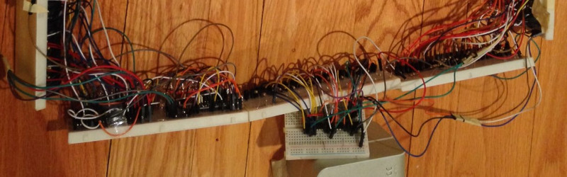
His hardware is built on twelve breadboards mounted in a square, upon which sit 144 LED/phototransistor pairs managed through a pile of 4051 CMOS multiplexers by a brace of Arduino Nanos. If you fancy one yourself he’s provided all the code, though the complex array of breadboards to assemble are probably not for the faint-hearted. You can see it in action in a video we’ve posted below the break.
This is a credible effort for a large pointing device, but it’s fair to say that the technology has moved on. We’ve previously shown you a look at multi-touch tables using an infra-red webcam, and if you want a really fancy one how about this Kinect-driven 3D display?


Hewlett-Packard’s HP-150 personal computer did this back in the 1980s. It was a good idea that wasn’t 100% IBM PC compatible, so of course it failed.
Microcomputers were so much more creative pre-IBM. I miss that.
While not strictly touchscreen, absolute pointing devices already existed in the late 70s (light guns).
And yes, IBM removed almost everything from computers, from their awesome sound chips to all sorts of game controllers. Even floppy drives were removed in early IBM PCs.
They weren’t removed, the first IBM PCs didn’t have floppies at all. They had a tape port. Like the dozens of other desktop computers at the time. If you wanted to pay something like the price of the PC over again, you could add a floppy or two, that was provided for from the start.
Most home computers, a floppy drive cost more than the computer did. In the UK, often twice as much.
I wonder why, actually. Towards the end, you could buy brand new floppy drives for five quid, or even three. Before that they were twenty, before that forty, before that, however much more.
The final drives were much more integrated, a lot of the mechanism, including the motors, were integrated into the frame. I can see why that made them cheaper. But still, how can something fall in price by a factor of a hundred? And yet still do exactly the same job, same technology.
Light pens were probably more common than light guns. Same thing, except a pen instead of a gun, obv. The IBM PC CGA card had a light pen input. Any idea how it worked? They usually interfaced to the video chip directly, which knew where the CRT’s beam was at any moment. But from what I recall, that wasn’t the case with the CGA card.
Surprised they weren’t more popular actually. Since a light pen is pretty much just a phototransistor in a tube. Not much hardware. Everything, in the PC’s case, was already included on the CGA card which came with the machine. So they could’ve been done really cheap.
I think a big part of why light pens weren’t more popular is the same “gorilla arm” syndrome that afflicts modern touchscreens when the screen is near vertical.
Simple: economy of scale.
HP used this on some of their test equipment. I remember using a touch-enabled logic analyzer. It had a green mono CRT, but it worked well.
Even the 1st generation Nook e-readers used this type of touch.
A lot of e-readers did, or still do. I can’t remember why, but there’s a good reason why a normal touchscreen won’t work with e-ink.
Perhaps the signals applied to the capacitive sensing electrodes and the signals applied to the electrodes used to control the black/white capsules in the electrophoretic display would interfere with each other. I’ve never examined a touch e-reader, so I didn’t actually know that any of them used this kind of touch sensing.
Thank you for commenting and reading the article. It’s true that infrared touch isn’t exactly any type of new technology. The point of this project was to use it to make a modular smart board that can send information wirelessly to its host computer. By modular, I mean that it has expansion modules that can be used to expand the touch area.
HP used the IR touchscreen scheme on their late ’80s and ’90s logic analyzer mainframes. Fortunately they provided a keyboard/mouse option (and later xdmcp over Ethernet) for those who don’t enjoy gorilla arm.
I worked at HP in their medical products division. We used the IR touchscreen from the HP-150 in a heart monitor.
Thanks for reading and commenting on the article. One of the issues I considered while making this project, is compatiblility between systems. Since the mouse is controlled by the Pro Micro, the interface is essentially compatible with linux (macOS too), and windows. As long as the computer had mouse drivers, the system can operate on it.
Our library’s terminals had these in the 80s.
They worked nicely over the 1/2 inch thick child-proof glass.
I believe IR touch is still used in some scenarios where very thick display glass is needed (e.g. To prevent abuse).
The PLATO system, developed at the University of Illinois and sold worldwide by Control Data Corporation, did this starting with the Plato IV plasma terminal.
If you are interested in building big touchscreens then you might want to visit:
http://nuigroup.com/forums
Mainly focused on IR + Vision based multi touch.
The idea is nice but touch sensitive screens are expected to be very sleek. I think that it would be difficult to achieve a sleek design using this.
I have a touch sensitive Dell monitor with an IR LED/Sensor array around the bezel. There are a few unexpected annoyances:
Wake on mouse click. A sheet of paper, a swinging cable or whatever can turn the computer on. Might be how cats upload videos to youtube.
Flying bugs can click links on web pages. Really.
Hello, thank you for spending the time to read and comment on the article. When I was working on the project, I programmed it to have a sort of software-based filter that recognizes and ignores random activation from objects such as shadows, bugs, and things such as palms and papers. The system adjusts it’s calibration when a significant change (such as a piece of paper) occurs. This is an attempt to maintain the integrity of the system.
I must be missing something here. If I get on aliexpress and search for “infrared touch screen”. I see multi-point 50″ touch bezel for less than $200, complete with USB interface. Why make your own?
Seriously? You are asking such question on Hackaday?
Hello, thank you all for reading the article and sharing your opinions about it. I also thank Ms. List for posting the article. I am writing this to clarify some of the questions that are in the comments of this article.
I understand that most see this project as not really an improvement to existing touch systems and some are even asking “what is the point”. The article gives a brief overview of the project and its features and I appreciate that. In order to understand the project fully, it is best to go to the Instructables ( https://www.instructables.com/id/Inexpensive-Wireless-Interactive-Board/ ) post or the Hackaday.io ( https://hackaday.io/project/21050-inexpensive-wireless-interactive-touch-interface ) article of the same title and read the description or the features column. The reason why I built this project is to make interactive touch boards more accessible whether it be for those who are in developing countries or those who cannot afford interactive touch boards in developed countries. This is why I aimed at making the project cheap to build ($50), another one of the features that I wanted to include was the ability to resize the interface. I did this by making the project modular which means that the user can add segments to the interface in the X or Y axis and resize it to their desired size and shape. The use of the extension modules and how they work with the system is described in both the Hackaday and Instructable articles. Yet another feature I wanted to include was the ability for the system to be wireless so that the interface does not have to be close to the computer that it is controlling (I did this because at my school I see teachers that sit and grade in the back of the classroom but they need to move their computer to the front of the room when teaching because the board is mounted to the front of the room and it relies on a wired connection). I established wireless communication using NRF radios between the sensors and the component that plugs into the computer being controlled. The final reason why I built this project was to make a touch interface that does not rely on drivers because they make moving the system between computers a hassle, so I wrote my own software as to avoid having to rely on OS touch drivers. These features are discussed in both of the other articles I posted this project on and just to make things a little more clear, I will be adding videos demonstrating the modular and wireless nature of the project.
Thank you again for reading this article.
You don’t need to justify your work, it’s a fantastic project!
I remember someone somewhere using a cmos strip from a scanner and LEDs to detect finger positions
Here, and it’s CCD to be precise ;)
http://hackaday.com/2011/03/21/converting-a-scanner-into-a-touchscreen/
Thanks :-)
It’s interesting to note the difference in attitude between different countries and our lack of appreciation and understanding of the issues facing those in other parts of the world.
We become very accustomed to the services and products available to us and the the disposable income to spend on gadgets. But this clearly is not a universal situation.
Well done Adellar on your excellent work.
Thank you very much Saabman, I highly appreciate this comment.
Thinking about doing this for a magic mirror, I’d put the components on the rear and have only the IR emitters/receivers in the frame around the edge, Just curious what the maximum distance is between the edges and how many modules/leds are the maximum.