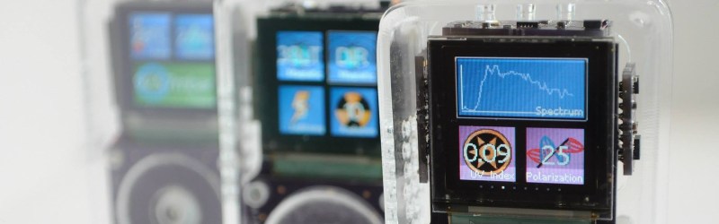
The hardware coming out of [Dr. Peter Jansen]’s lab is the craziest stuff you can imagine. He’s built a CT scanner out of plywood, and an MRI machine out of many, many turns of enamel wire. Perhaps his best-known build is his Tricorder – a real, all-sensing device with permission from the estate of [Gene Roddenberry] to use the name. [Peter]’s tricorder was one of the finalists for the first Hackaday Prize, but that doesn’t mean he’s stopped working on it. Sensors are always getting better, and by sometime in the 23rd century, he’ll be able to fit a neutrino detector inside a tiny hand-held device.
One of the new sensors [Peter] is working with is the MAX30105 air particle sensor. The marketing materials for this chip say it’s designed for smoke detectors and fire alarms, but this is really one of the smallest dust and particle sensors on the market. If you want a handheld device that detects dust, this should be the chip you’re looking at.
Unfortunately, Maxim is being very, very tight-lipped about how this particle sensor works. There is a way to get access to raw particle counts and the underlying algorithms, and Maxim is more than willing to sell those algorithms through a third-party distributor. That’s simply not how we do things around here, so [Peter] is looking for someone with a fancy particle sensor to collect a few hours of data so he can build a driver for this chip.
Here’s what we know about the MAX30105 air particle sensor. There are three LEDs inside this chip (red, IR, and green), and an optical sensor underneath a piece of glass. The chip drives the LEDs, light reflects off smoke particles, and enters the optical sensor. From there, magic algorithms turn this into a number corresponding to a particle count. [Peter]’s hackaday.io log for this project has tons of data, math, and statistics on the data that comes out of this sensor. He’s also built a test rig to compare this sensor with other particle sensors (the DSM501A and Sharp sensors). The data from the Maxim sensor looks good, but it’s not good enough for a Tricorder. This is where you, o reader of Hackaday, come in.
[Peter] is looking for someone with access to a fancy particle sensor to collect a few hours worth of data with this Maxim sensor in a test rig. Once that’s done, a few statistical tests should be enough to verify the work done so far and build a driver for this sensor. Then, [Peter] will be able to play around with this sensor and hopefully make a very cheap but very accurate air particle sensor that should be hanging on the wall of your shop.


Why on earth would you design something with a maxim part, fuck those guys. Good luck getting qtd less than 5k
Wait…Maxim developed something that they will sell you with no way to make it work other than reverse engineering? Isn’t that a little bassackwards in the profit arena?
I assume you can opt for the normal NDA backed up by remote triggered cyanide capsule installed in your first born.
You don’t want to go a displease Maxim,
https://www.youtube.com/watch?v=m-KESpTStok
This seems more like an FTDI tactic
The device works fine. Here’s the datasheet.
http://datasheets.maximintegrated.com/en/ds/MAX30105.pdf
There’s an extra layer of computer science on the host processor which helps interpret those I2C register readouts into a “smoke alarm activated” condition, quickly and accurately but without false positives, and that’s proprietary, and that’s what he wants to reinvent.
http://www.valorfiresafety.com/licensing/
It’s intended as a smoke alarm – it’s not intended as a dust particle counter for use in (e.g.) cleanroom environments.
I concur. The device is designed to detect Tyndall scattering, specifically from smoke in air, evaluating backscatter from the LEDs.
If you want to use it for a particle detector (pm 2.5, pm 10), you’ll be doing geometric optics, with a hard limit on the maximum particle density, as determined by flow rate and pulse width of the LEDS. Your ability to differentiate between particles of difference sizes will depend on your being able to observe samples that are more likely than not to contain the backscatter from a single particle.
You might have to flow some particle-free gas (filtered) with the sample to dilute it down enough to get those single particle events.
That’s where I’d start, anyway.
Hmm. I never knew they had a reputation for that. I always found them quite agreeable (never problems with free samples, data sheets are decent). I even designed something with one of their silicon processes once (cb2 I think it was called, 1/2 micron, good BJT’s).
Welcome to the world of less than savory corporate politics and BS that infects the parts of the industry.
My understanding of a tricorder isn’t just the passive part, but active sensing as well, combined with huge data-banks and AI.
Interestingly the tricorder in Startrek always was envisioned as an intelligent device with it’s own miniature computer and storage.
Sharp GP2Y10 also?
Wow someone should hack this chip to perform raman and IR absorption measurements
Don’t blame Maxim-Integrated for being “Closed” on how this part works internally. If Maxim was as “Open” as you want, then Chinese “Fakes” will show-up PDQ with complete disregard to the protection of Intellectual Property rights. It takes money to develop something new. It takes far-less money to copy and sell it. And Maxim will have no recourse without true Rule-of-Law in the offending country.
As it turns out I’ve just been given access to park some commodity PM2.5 sensors next to EPA-managed calibrated instruments to see if we can characterize the performance of several low-cost units currently on the market vs the far more expensive (and difficult to maintain) gear.
The MAX30105 is very poorly documented, but a mostly identical chip is ‘well’ documented – see the MAX30102. Critically, the MAX30102 has the same sensor, the same LEDs, and the same thermal compensation routines. Briefly, to make sense of the MAX30105:
1/ Measure temp.
2/ Use temp to thermally compensate the three optical channels.
3/ Subtract the means off of all three optical channels.
4/ Now, compute the ratios of the various channels, such as Ch1/Ch2 etc.
The thermal compensation step is critical, since the peak wavelength of the LEDs drift with temperature etc. Note also that the QE of the detector needs to be taken into account, otherwise the signal magnitudes are screwed up in ways I have not figured out yet. The key starting point for reverse engineering the MAX30105 is this block of code from the Maxim github:
https://github.com/MaximIntegratedRefDesTeam/RD117_ARDUINO/blob/master/algorithm.cpp
// calculates DC mean and subtract DC from ir
un_ir_mean =0;
for (k=0 ; k<n_ir_buffer_length ; k++ ) un_ir_mean += pun_ir_buffer[k] ;
un_ir_mean =un_ir_mean/n_ir_buffer_length ;
// remove DC and invert signal so that we can use peak detector as valley detector
for (k=0 ; k<n_ir_buffer_length ; k++ )
an_x[k] = -1*(pun_ir_buffer[k] – un_ir_mean) ;
// 4 pt Moving Average
for(k=0; k< BUFFER_SIZE-MA4_SIZE; k++){
an_x[k]=( an_x[k]+an_x[k+1]+ an_x[k+2]+ an_x[k+3])/(int)4;
}
// calculate threshold
n_th1=0;
for ( k=0 ; k<BUFFER_SIZE ;k++){
n_th1 += an_x[k];
}
n_th1= n_th1/ ( BUFFER_SIZE);
if( n_th160) n_th1=60; // max allowed
If I understand your project you are planning/hoping to get particle size. Laser seems the way to go…shining two wavelengths can get us only so much info. I am interested to hear feedback because I am in this business and have a big client coming to see my wares in a few days…! Currently we use Sensirion and some other local outfit.. plantronics I think it is. If there are any experts out there I have some work.
There is a similar sensor from Analog Device: the ADPD188-BIZ and a very good application note on tests done on different kind of smoke. Regardint the chip It is quite difficult to understand and properly set all registers but the ADPD1080 datasheet is a bit clearer on the definitions.