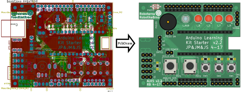
If you’re producing documentation for a PCB project, you might as well make the board renders look good. But then, that’s a lot of work and you’re not an artist. Enter [Jan]’s new tool that takes KiCad board files, replaces each footprint with (custom) graphics, and provides a nice SVG representation, ready for labelling. If you like the output of a Fritzing layout, but have higher expectations of the PCB tool, this is just the ticket.
 We all love [pighixx]’s pinout diagrams. Here’s his take on the Arduino Uno, for instance. It turns out that he does these largely by hand. That’s art for ya.
Sparkfun has taken a stab at replicating the graphical style for the pin labels, but then they toss in a photo of the real item. [Jan]’s graphic PCB generator fills in the last step toward almost putting [pighixx] out of a job. Get the code for yourself on GitHub.


I like that!!
Though, I must, politically, mention that I’d much rather see the kicad 3D footprint libraries being extended – and then used to render the board isometrically from the top:

It’s obvious I haven’t made 3D models for my custom button footprint, and the strange 1mm-pitched IC package, as well as the missing 3D footprint of the screw terminal from the stock libraries.
Advantage of adding 3D models: Use the same for non-top-renders:
Disadvantage: it’s a render, not a vector graphic.
Non-top render got lost in the shuffle:
http://i.imgur.com/L3c6AQT.png
Also, note that the 3D renderer comes built-in to Kicad.
They’re complementary features. A 2d render as a base for a clean pinout diagram is useful.
I just wish the toolchain for creating 3d models for kicad wasn’t so awful.
Or just use Altium Designer…
Had too much problems with KiCad, that I am using it only for checking old projects….
Can altium output such a 2d graphic? I’ve only seen it do 3d step files. Perhaps the altium file format can be converted to kicad_pcb?
This post remins me of one of the board photos of Sigrok:
http://www.sigrok.org/wiki/File:DDS120_Top_20141024_0540p.jpg
The way that the traces and IC footprints are overlayed over the photograph looks way to neat for a casual job.
So it must have taken a lot of time or it must have been done by someone wiht a lot experience in this stuff.
Does anyone know if there are (open source?) reverse engineer tools available for work like this?
That image of the SainSmart DDS120 from the sigrok wiki appears to have originated with [doctormord] in this forum thread:
https://www.eevblog.com/forum/testgear/sainsmart-dds120-usb-oscilloscope-%28buudai-bm102%29/75/
As the thread progresses, [doctormord] removes the Cypress FX2 processor and adds new details to the trace overlay in the image. The way this is done makes me believe that the overlay was (painstakingly) constructed manually, and not through use of reverse-engineering software.
I personally use Eagle-Up. 3D boards in SketchUp from eagle files. Granted you need to add your own components but it makes nice looking boards.
The nightly builds of KICAD added support for a raytracing engine in addition to the legacy OPENGL. The results look great as per my use and should be released in version 5 according to the developers talk at FOSDEM. STEP import and export was added too.