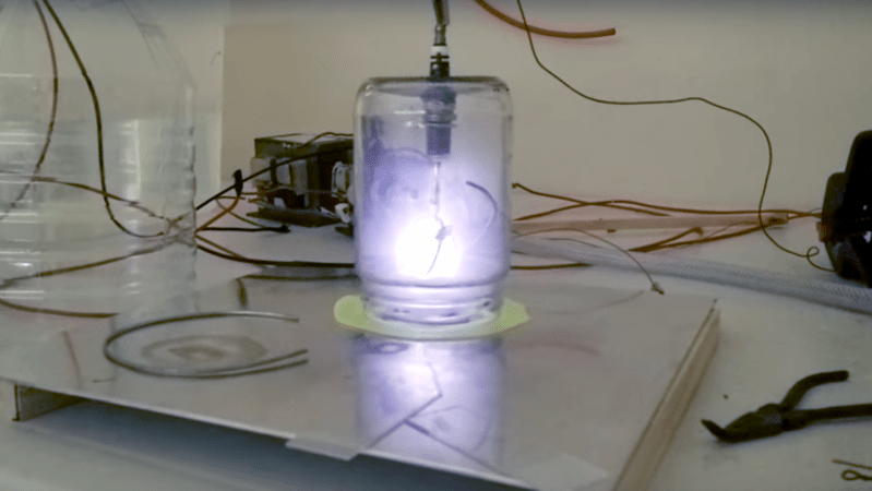
Fair warning: [Justin Atkin]’s video on how to make plasma, fusors, and magnetrons is a bit long. But it’s worth watching because he’s laying a foundation for a series of experiments with plasma, which looks like it will be a lot of fun.
After a nice primer on the physics of plasma, [Justin] goes into some detail about the basic tools of the trade: high voltage and high vacuum. A couple of scrap microwave oven transformers, a bridge rectifier, and a capacitor provide the 2000 volts DC output needed. It’s a workable setup, but we’ll take issue with the incredibly dangerous “scariac” autotransformer, popularized by [The King of Random]. It seems foolish to risk a painful death mixing water and line current when a 20-amp variac can be had for $100.
A decent vacuum pump will be needed too, of course; perhaps the money you can save by building your own Sprengel vacuum pump can be put toward the electrical budget. Vacuum chambers are cheap too — Mason jars with ground rims and holes drilled for accessories like spark plugs. Magnets mounted below one chamber formed a rudimentary magnetron, thankfully without the resonating cavities needed for producing microwaves. Another experiment attempted vapor deposition of titanium nitride.
It’s all pretty cool stuff, and we’re looking forward to more details and results. While we wait, feel free to check out the tons of plasma projects we’ve featured, from tiny plasma speakers to giant plasma tubes.


Because instead of using the variac, he is using 2 pieces of carbon rod dipped in a bucket of NaOH as a variable resistor. AKA the ‘scariac’
mmm, x rays
This, electrical arc in a vacuum is a electron gun or x-ray generator or death ray. Fire is the safest choice for plasma in this situation. We should put something like danger x-rays on this article, because the video and article say nothing about it.
No xrays are produced so there was no warning given. Xrays are only generated above 10kv which this doesn’t even come close to. We double checked with a Geiger counter to confirm and didn’t detect anything above background
What model of Geiger counter may I ask? There are several types, and very few cheap-end ones are affected by X-rays.
Its a custom model made by one of the guys on the fusion forums and wasn’t cheap. I’ve checked it and its plenty sensitive to xrays. Its got a mica window and everything so it can do everything from alpha to gamma.
I’m fairly certain cheap geiger tubes are very susceptible to x-rays. It’s ionizing radiation that is more penetrating than alpha.
A scintillation counter may be more variable. Some of the high end ones have narrow energies that will register.
Something something: most gm tubes are overly sensitive to gamma/beta in low energies. That is why you have to buy “dose compensated” gm tubes. It ends up knocking out a considerable amount of low energy to even out the non linearity of the dose rate. Scintillation detectors are great except for low energies (mostly limited by the noise in your electronics) and high dose rates (they saturate). What you are talking about is likely the fact that they are working in a proportional region, as such, you can determine the incoming energy amount (and do isotope identification).
Of course they do. In the video they say that its dangerous to build a larger fusor and flash up pictures of what is required before starting. The pictures are Geiger counters. These are safe from an xray point of view.
The “scariac” is not an autotransformer, but a liquid rheostat. The reason we like to use variable autotransformers instead of rheostats, or resistive control in general, is because rheostats dump the excess voltage as heat; the scariac is a big step backwards for most applications where you can use a variac. (Of course, it’s got built-in water-cooling, so it can handle the heat to a point. Don’t let it boil, though, as that both interferes with conduction and splashes dilute lye everywhere.) So please don’t call it an autotransformer.
While the shock hazard of the scariac is obvious, a less obvious concern involves the effect of evaporation. The concentration of lye will increase as water evaporates, making the solution more conductive and increasing current — there seems to be a risk of thermal runaway here. But since evaporation also decreases the submerged area, which would decrease current, I’m not sure which dominates, or more usefully, what setup (depth of immersion and concentration) would balance the effects for the best stability. Without figuring this out, one would want to be even more cautious than usual about leaving it unattended.
Liquid rheostats have been used in industry, though they are less common now, so there might be good information out there on how to ensure stability under evaporation. I know one solution used is to put an oil layer on top of the electrolyte to suppress evaporation. And even when this isn’t used, since they’re working on a larger scale, the square-cube law is their friend — proportionally less surface area for evaporation makes it less of a problem, so the only advice might be to check the electrolyte level once a shift and top it up if needed. Still, worth looking into if you decide to build something like this.
The major change we made was to not use lye and to use baking soda instead. Works very well and removes the caustic issue. Also we never ran it long enough that it got hot. Never even saw steam.
Heh heh, hokay, so after you’ve bubbled off all the carbonate as CO2, what do you think is in there when you’ve got Sodium and Hydroxide ions left ???
If 20 minutes is a bit long, then we shouldn’t be hacking in the first place. I count time in days not minutes.
Try Years
Great video.